


- 36 -
Copyright ©2008 LG Electronics. Inc. All right reserved.
Only for training and service purposes
LGE Internal Use Only
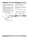
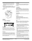
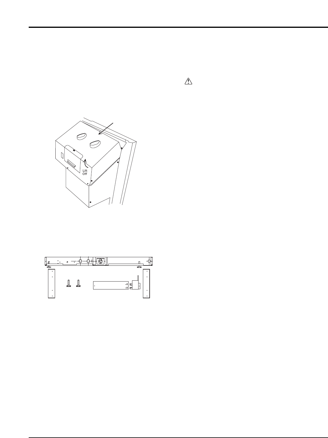
5. Replace the escutcheon with the one from this kit by
inserting the tabs at the top of the escutcheon into the
retaining holes and laying the escutcheon flat on the
control panel.
6. Replace the front by reversing steps 1 through 4.
7. Store the control knobs and escutcheon just removed from
the unit for possible reinstallation if the wall thermostat is
no longer desired.
Subbase
Part No: AYSB1101 (230/208V 20A)
AYSB2101 (230/208V 30A)
Description
The subbase may be installed on the wall sleeve before or
after installing the wall sleeve. The subbase is prewired.
Electrical connections can be made on the left side after the
access cover is removed. A grounding screw is provided.
Receiving
Upon receipt of the product, inspect the shipping carton for
signs of visible damage. Report any damage or shortage to
the carrier and note it on the delivery receipt. The unit must
be stored in its original shipping carton in a dry, secure place
prior to its installation and use.
Installation
The installation and servicing of the equipment referred to in
this booklet should be performed by qualified, experienced
technicians.
WARNING
Hazardous Voltage!
Disconnect all electric power, including remote disconnects
before servicing. Follow proper lockout/ tagout procedures to
ensure the power can not be inadvertently energized. Failure
to disconnect power before servicing could result in death or
serious injury.
Important Note:
The unit OFF switch does not disconnect all electrical power
to this unit.
CAUTION
Use Copper Conductors Only!
Unit terminals are not designed to accept other types of
conductors. Failure to use copper conductors may result in
equipment damage.
Note:
When using a subbase, the wall sleeve must be installed a
minimum of 3-
1
/4 inches (83 mm) above a finished floor and a
minimum of 2-
3
/
4 inches (70 mm) from a finished wall.
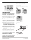
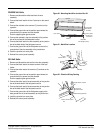
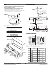
1. Remove parts B and C (Figure 58, next page) from the
subbase and join together using two metal screws provided.
This assembly now becomes the right front cover (Part F) of
the subbase. (Figure 57, next page)
2. Position subbase under the front of the wall sleeve.
3. Align the back edge of the flange on cover A (Figure 58, next
page) to front of the wall sleeve flange. (Figure 59, next
page)
4. Drill four 1/8 inch holes in wall sleeve to line up with holes in
subbase. (Figure 58, Location D, next page) Mount subbase
to wall sleeve with four sheet metal screws provided with kit.
(Figure 58, Location D, next page)
5. Remove the left front cover from the subbase. (Figure 58,
Part A, next page)
6. Position skirting on each side of wall sleeve to prevent the
entry of foreign materials. Trim skirting to desired length.
Attach skirting with four sheet metal screws provided with kit.
(Figure 58, Location E, next page)
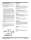
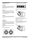
7. Wire subbase for appropriate voltage (Figure 60, next page).
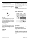
Escutcheon
Figure 56