


- 31 -
Copyright ©2008 LG Electronics. Inc. All right reserved.
Only for training and service purposes
LGE Internal Use Only
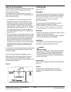
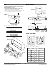
Indoor Drain Kit Installation
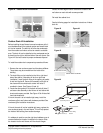
The internal drain is installed on the bottom of the wall sleeve
when it is required to drain the condensate into a drain
system inside of the building.
The components of the wall sleeve drain kit are shown in
Detail A. Use components C (2), D, E, mounting screws (6)
and the Outdoor drain fitting.
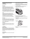
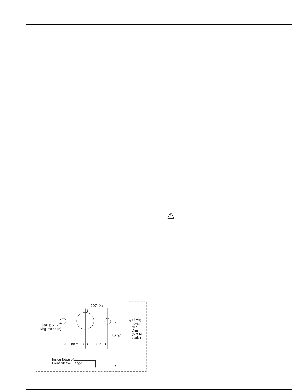
1. The components D, E, and drain fitting of the kit are
mounted on the bottom of the wall sleeve prior to the
installation of the sleeve. It may be located in a feasible
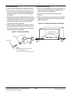
area on the bottom of the sleeve which is inside of the
room except when a subbase is used. When a subbase is
installed, the drain may be a minimum of 3 1/2 " from the
front flange of the wall sleeve. The minimum clearance
should provide adequate clearance for the subbase, see
Figures 46 and 47.
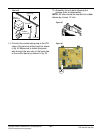
2. Cut out the template in the lower right hand corner of these
instructions to locate the field drilled holes. (Two to mount
the plate and one for the Outdoor drain fitting). See Detail
A on how the components have to be installed after the
holes are drilled in the bottom of the wall sleeve. If the
drain fitting is not connected to an indoor drainage system
immediately after the wall sleeve is installed, it must be
plugged with a cork to prevent indoor water damage in
case it rains.
An indoor tube or hose (furnished by others) must be installed
on the drain fitting and interconnected to the drain system
inside of the building.
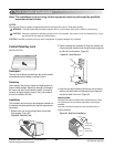
Install the two blank-off plates C and gaskets A on the
outdoor portion of the wall sleeve as shown in Figure 46.
These components may be installed after the sleeve is
secured in the wall opening just prior to the installation of the
condenser grille and chassis.
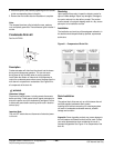
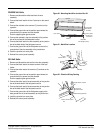
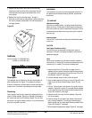
Leveling Legs
Part No: AYLL101
Description
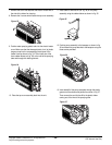
Leveling legs are designed to provide extra front support and
leveling of the wall sleeve. Two leg assemblies are required
per unit and are provided in each kit. Four screws are also
provided with each kit for attachment to the wall
sleeve. See Figure 48.
The leveling legs must be installed before the chassis is
installed, but after the wall sleeve is in place.
Holes must be drilled in each side of the wall sleeve, below
the duct package holes, for attachment to the wall sleeve.
Receiving
• Compare kit identification number with sales order to ensure
that the correct kit has been received.
• Inspect the leveling legs for shipping damage. File damage
claims with the delivering carrier immediately.
Installation
The installation and servicing of this equipment should be
performed by qualified, experienced technicians.
Important Note:
The unit OFF switch does not disconnect all electrical power
to this unit.
Checklist
The following is an abbreviated guide to leveling leg
installation. Refer to appropriate areas for more detailed
information.
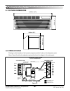
Figure 47
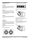
WARNING
Hazardous Voltage!
Disconnect all electric power, including remote disconnects
before servicing. Follow proper lockout/tagout procedures
to ensure the power can not be inadvertently energized.
Failure to disconnect power before servicing could result in
death or serious injury.