


- 34 -
Copyright ©2008 LG Electronics. Inc. All right reserved.
Only for training and service purposes
LGE Internal Use Only
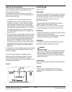
208/230 Volt Units
1. Remove and discard the white lead from the wire
assembly.
2. Connect the black lead to the line 2 terminal on the control
board.
3. Connect the red lead to the common (C) terminal on the
capacitor.
4. Connect the ground wire to the partition panel where the
ground wire on the power cord was located.
Use the supplied green ground screw.
5. Connect the red lead in the wire assembly at the junction
box to the red lead of the field power source.
6. Connect the black lead in the wire assembly at the junction
box to the black lead of the field power source.
7. Connect the ground wire of the field power source to the
ground wire of the wire assembly at the junction box.
8. Install the junction box cover plate.
9. Reinstall the control panel assembly.
265 Volt Units
1. Remove and discard the red lead from the wire assembly .
2. Connect the black lead to the center terminal of the fuse
holder.
3. Connect the white lead to the common (C) terminal on the
capacitor.
4. Connect the ground wire to the partition panel where the
ground wire on the power cord was located.
Use the supplied green ground screw.
5. Connect the white lead of the wire assembly at the junction
box to the white lead of the field power source.
6. Connect the black lead of the wire assembly at the junction
box to the black lead of the field power source.
7. Connect the ground wire of the field power supply to the
bare ground wire of the wire assembly at the junction box.
8. Install the junction box cover plate.
9. Reinstall the control panel assembly.
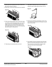
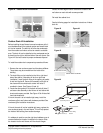
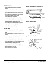
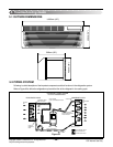
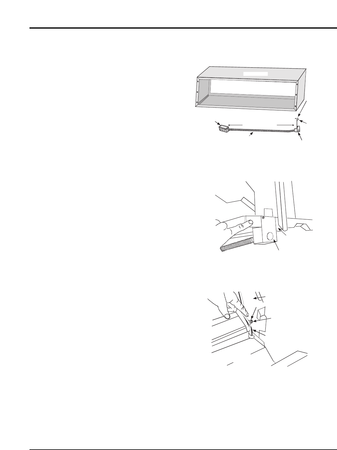
Wall Sleeve
Cover plate
Control Panel
Base Pan
Bracket
Right Side of Chassis
3/16 Inch
Diamenter Hole
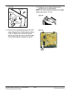
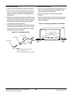
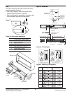
Back of Control Panel
Electrical Supply Wires
Ground Wie
with Eyelet
Terminal
Power Leads
with Push on
Connectors
Metal Box
with Straight Clamp
Conduit
28 Inch es Max
Wire Tie
Figure 52 - Electrical Wiring Routing
Figure 51 - Metal Box Location
Figure 50 - Mounting Hard Wire Junction Box Kit