


- 33 -
Copyright ©2008 LG Electronics. Inc. All right reserved.
Only for training and service purposes
LGE Internal Use Only
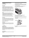
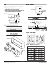
Hard Wire Kit
Part No: AYAGALA01
Description
Hard Wire Junction Box (Direct Wire Sub-Base) The hard wire
junction box kit is used to hard wire the unit when it is not
desirable to use the standard unit subbase or the unit power
cord.
The junction box provides a protected enclosure for electrical
connections as required by some electrical codes.
The hard wire junction box is intended to be mounted on the
floor or the adjacent wall.
The junction box is furnished with approximately 2-1/2 feet of
1/2-inch flexible steel conduit and a metal box for securing the
conduit to the unit cabinet at the incoming power opening.
An optional 230/208V or 265V power switch assembly is
available for use with the hard wire junction box or subbase.
The switch provides a POWER ON/OFF function at the unit
as required by some electrical codes.
A replacement junction box cover plate is provided with each
switch kit.
For additional information, refer to the Power Switch
Installation Instructions.
Receiving
Upon receipt of the product, inspect the shipping carton for
signs of visible damage. Report any damage or shortage to
the carrier and note it on the delivery receipt. Unit must be
stored in its original shipping carton in a dry, secure place
prior to its installation and use.
Installation
The installation and servicing of this equipment should
performed by qualified, experienced technicians.
Junction Box Kit Installation and Wiring
Procedure
EIectrical connections at the unit must be made after the unit
chassis is installed in the wall sleeve. The installer must
determine and supply the mounting components for attaching
the junction box to the wall or door.
WARNING
Hazardous Voltage!
Disconnect all electric power, including remote disconnects
before servicing. Follow proper lockout/tagout procedures to
ensure the power can not be inadvertently energized. Failure
to disconnect power before servicing could result in death or
serious injury.
Important Note:
The unit OFF switch does not disconnect all electrical power
to this unit.
CAUTION
Use Copper Conductors Only!
Unit terminals are not designed to accept other types of
conductors. Failure to use copper conductors may result in
equipment damage.
Important Note:
All wiring must comply with applicable
local and national codes. Types and location of disconnect
switches must comply with all applicable codes.
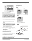
1. Remove the cover plate from the junction box
2. Mount the junction box to the wall or floor within 28 inches (711
mm) of the lower right corner of the wall sleeve.
3. If a disconnect switch is to be used, make electrical
connections to it and mount the switch in the junction box.
Refer to the Power Switch Installation Instructions.
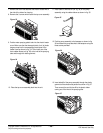
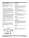
4. Remove control panel assembly by removing the two screws
holding control panel in place. Rotate the panel forward.
5. Disconnect the power cord leads from all electrical connections
including the ground wire.
6. Remove the power cord clamp and the power cord from the
unit.
7. For 208/230-volt units, remove and discard the white lead from
the wire assembly. For 265-volt units, remove and discard the
red lead from the wire assembly.
8. Remove the retaining ring from the threaded portion of the
straight conduit clamp. Insert the three wires into the metal box
through one of the two openings in the box. Replace the hole
cover grommet into the unused hole to prevent objects from
entering the box.
9. Replace the retaining ring back on the conduit clamp inside the
metal box and tighten the ring securely.
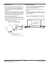
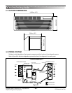
10. Insert the three wires extending from the metal box into the
incoming power opening on the unit so that approximately 20
inches (508 mm) of the wires protrude through the opening.
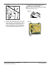
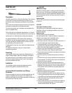
11. Attach the metal box to the chassis with the two screws
provided. See Figure 50.
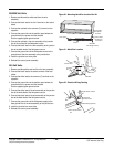
12. Insert the wire tie into the 1/4-inch diameter hole located just
above the incoming power opening. Tie all wires together
securely with the wire tie. See Figure 51.