


8
INSTALLATION - SYSTEM PIPING
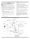
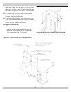
Recommended near boiler piping for gravity return
4.
systems is shown in Figure 5. This confi guration uses
one supply and one return tapping. This setup can be
used on any size boiler in this series. The supply and
return connections may be piped both into the same
side (either left or right) or one into each side of the
boiler.
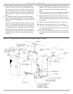
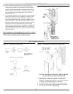
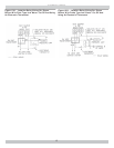
For installers choosing to use both supply tappings,
5.
Figure 6A shows the correct way to pipe this system.
Figure 6B shows the wrong way to pipe a header with
two risers.
Headers must be fi tted with header offsets or swing •
joints, or be equipped with expansion joints, so that
thermal expansion and contraction of the header will
not damage the boiler. Headers shall not be welded.
System takeoffs from the header must be between •
the equalizer and the riser to the header nearest the
equalizer. System takeoffs must never be between
two risers.
System takeoffs from the header must never be bull-
6.
headed. If the steam main goes in two directions, there
must be two takeoffs from
the header, one for each
main.
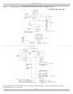
All boilers in gravity return systems
7.
must be equipped
with a Hartford Loop as shown in Figures 2 and 3A.
When piping the vertical risers from the boiler to the
8.
header, the bottom of the header must be a minimum
of 24 inches above the water level line on the right side
of the boiler.
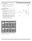
Steam riser(s) and header shall be 2-1/2” pipe size.
9.
Equalizer line shall be minimum 1-1/2” pipe size.
10.
The near boiler piping shall include a 2-1/2” tee with a
11.
plug located on the supply line as shown for skimming
(i.e. surface blowdown).
The near boiler piping shall include a 1-1/2 ball valve
12.
in the return piping as shown for bottom blowdown and
draining.
Figure 3A - Recommended Near Boiler Piping Using One Supply Tapping