


14
ELECTRICAL WIRING
ELECTRIC POWER SUPPLY
Electrically bond boiler to ground in accordance with
requirements of authority having jurisdiction. Refer to:
USA- National Electrical Code, ANSI/NFPA 70.•
Canada - Canadian Electrical Code, Part I, CSA C22.1: •
Safety Standard for Electrical Installations.
Run separate 115 volt circuit from separate overcurrent
protective device in your electrical service entrance panel.
This should be 15 ampere circuit. Locate shut-off switch
at boiler. It must be turned off during any maintenance.
Connect 115 volt electrical supply to primary leads on 24
volt transformer. Solder and tape or securely fasten these
connections with wire nuts.
Boiler, when installed, must be electrically grounded in
accordance with requirements of the authority having
jurisdiction or, in absence of such requirements, with
National Electrical Code, ANSI/NFPA No. 70 and/or
Canadian Electrical Code, Part I, CSA C22.1: Safety
Standard for Electrical Installations. Run 14 gauge or
heavier copper wire from boiler to grounded connection in
service panel or properly driven and electrically grounded
ground rod.
!
WARNING
Turn off electrical power at fuse box before
making any line voltage connections. Follow
local electrical codes.
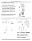
INSTALL YOUR THERMOSTAT
Thermostat location has important effect on
operation of your boiler system. BE SURE TO FOLLOW
INSTRUCTIONS INCLUDED WITH YOUR THERMOSTAT.
Locate thermostat about fi ve feet above fl oor on inside
wall. It may be mounted directly on wall or on vertically
mounted outlet box. It should be sensing average room
temperature, avoid following:
DEAD SPOTS:
Behind doors
Corners and alcoves
HOT SPOTS:
Concealed pipes
Fireplace
TV sets
Radios
Lamps
Direct sunlight
Kitchens
COLD SPOTS:
Concealed pipes or ducts
Stairwells - drafts
Doors – drafts
Unheated rooms on other side of wall
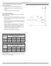
Set heat anticipator at 0.4 amps for boilers equipped
with standing pilot, and at 0.6 amps for boilers equipped
with intermittent ignition. Connect 24 volt thermostat
leads to two wires tagged “24 volt thermostat” on boiler.
For boilers with 67D-1 fl oat type low water cut-off, two
wires are black. One wire is located on secondary of 24
volt transformer, second wire is located on pressure limit
control. For boilers with PS-802 probe type low water
cut-off, one wire is green and is located on terminal B of
PS-802, second wire is black and located on pressure limit
control.
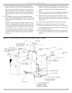
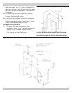
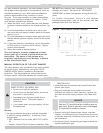
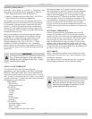
ELECTRONIC THERMOSTATS
Certain types of electronic thermostats may lose their
memory or shut down. With 67D-1 fl oat type low water
cutoffs, this may occur each time thermostat calls for heat,
due to internal circuit in vent damper. With PS-802 probe
type low water cut off’s, this may occur each time low
water cut off detects low water condition. If this is case,
isolation relay is required for thermostat circuit. 24 volt
single pole single throw (SPST) normally open (N.O.) relay
is required, such as Honeywell R8222A or equivalent. Wire
as shown in Fig. 10A or Fig. 10B.
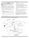
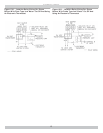
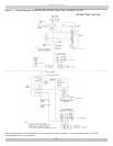
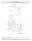
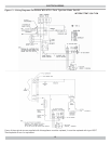
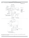
VENT DAMPER
Boiler is equipped with factory wired harness with 4 pin
molex plug, that plugs into 4 pin molex receptacle inside
vent damper operator.
Vent damper must be connected for boiler to operate.
Wiring diagrams follow for various different models.
!
CAUTION
Label all wires prior to disconnection when
servicing controls. Wiring errors can cause
improper and dangerous operation. Verify
proper operation after servicing.