


25
CHECKING AND ADJUSTING
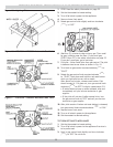
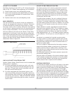
ADJUST PILOT BURNER
Pilot fl ame should surround 3/8” to 1/2” of the pilot sensor.
Refer to Fig. 19. If fl ame needs adjusting, do it as follows:
Remove screw cover over pilot adjusting screw.
1.
Insert small screwdriver and adjust fl ame as needed.
2.
Turn screw counterclockwise to increase fl ame, clock-
wise to decrease.
Replace screw cover over pilot adjusting screw.
3.
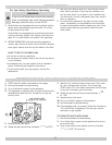
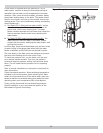
MAIN BURNER(S)
The main burners do not require primary air adjustment
and are not equipped with primary air shutters. Main burn-
er fl ames should form sharp blue inner cones in a softer
blue outer mantel, with no yellow. Puffs of air from blowing
on the fl ame or stamping on the fl oor will cause the fl ames
to turn orange momentarily. This is not unusual. Remain
still when observing the main burner fl ames. If the fl ame
appearance is not correct, check main burner orifi ces and
the burner throat and fl ame ports for dust and lint obstruc-
tion. It may be necessary to remove the rollout shield to
observe the main burner fl ames. Replace rollout shield after
observation. Refer to Figure 18.
Figure 18 - Main Burner
GAS VALVE SAFETY SHUTDOWN TEST
Ignition System Safety Shutoff device must be tested after
placing boiler in operation.
For boilers equipped with continuous pilot, with main
1.
burners fi ring, disconnect the thermocouple from the
gas valve. The gas valve should immediately shut off
the main burners and the pilot.
For boilers equipped with intermittent ignition, with
2.
main burners fi ring, disconnect the ignition cable from
the intermittent pilot control box. The gas valve should
shut off the main burners. TURN OFF ELECTRIC POWER
to boiler before reconnecting ignition cable, to prevent
electric shock.
ADJUST STEAM PRESSURE CONTROL
The steam pressure limit control (pressuretrol) shuts off
the gas to the main burners when the steam pressure in
the boiler reaches the cut-off setpoint (i.e. the sum of the
cut-in and the differential setpoints). Burners refi re when
the steam pressure drops to the cut-in setpoint. System
pressure requirements are based on the size and condition
of the pipes, and the load.
For good system operation, the cut-in setting of the pres-
suretrol should never be less than twice the system pres-
sure drop. In a typical single family residence with a clean
one pipe heating system and cast iron radiation, this means
that the cut-in will usually be set at the minimum setting,
i.e. 1/2 psi.
Steam radiation is usually sized based on square feet of
equivalent direct radiation (EDR). This is based on a steam
pressure in the radiator of just less than 1 psi. Therefore, in
our example system from above, we would set the differ-
ential adjustment at 1 psi, i.e. the steam pressure required
in the radiators. This will give us a cut-off setpoint of 1-1/2
psi.
The above is an example of a typical one pipe system.
For larger systems or other types of systems such as two
pipe systems, or systems with convectors or fan coil units,
the pressuretrol settings will need to be determined on a
system-by-system basis.
The cut-in setpoint is determined by the system pressure
drop to the furthest radiator or terminal unit. Double the
system pressure drop as a safety factor, resulting in the
rule that the cut-in setting should never be less than twice
the system pressure drop.
The differential setpoint is the steam pressure required at
the terminal heating units.
Now your boiler will operate in the correct pressure range.
It will maintain enough steam pressure to send the steam
out to the furthest radiator, and not go over the optimum
steam pressure that is required at the radiators.
CHECKING CONTROLS
To check the Low Water Cut-Off, turn off power to the boiler
or turn the thermostat down to the lowest setting. Drain
water to below the visible bottom of the water gauge glass.
Turn power on and turn the thermostat to call for heat.
When the boiler is equipped with the fl oat type LWCO the
gas valve should not open on a call for heat when the water
is low. When the boiler is equipped with a probe type LWCO
the gas control should be powered for approximately 10
seconds (the time delay on the probe type LWCO), then the
gas valve will close and the red indicator will illuminate on
the LWCO.