


10
CHIMNEY AND VENT PIPE CONNECTION
For boilers for connection to gas vents or chimneys, vent
installations shall be in accordance with National Fuel
Gas Code, ANSI Z223.1/NFPA 54, or "Venting Systems
and Air Supply for Appliances," of the Natural Gas and
Propane Installation Code, CAN/CSA B149.1, or applicable
provisions of the local building codes.
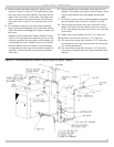
CHECK YOUR CHIMNEY
This is a very important part of your heating system. It
must be clean, the right size, properly constructed and in
GOOD CONDITION. No boiler can function properly with
a bad chimney. Inspect the chimney and verify that the
construction and size of the chimney meets all applicable
provisions of the National Fuel Gas Code and local building
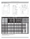
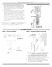
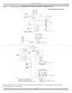
codes. Figure 4 gives you an idea how a boiler might be
vented to a chimney. Note that the height (HT) is measured
from the vent pipe to the top.
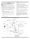
CONNECTING THE VENT DAMPER AND VENT
CONNECTOR
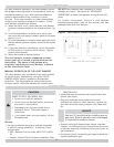
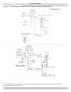
Refer to Fig. 1 and Table 1 for the size and location of the
vent (fl ue opening). Use a 28 gauge (minimum) galvanized
pipe to connect to the chimney.
IMPORTANT - The damper blade on the furnished vent
damper has a 1/2 square inch hole (approximately 3/4”
diameter). On boilers equipped with standing pilot, the hole
must be left open. On boilers equipped with intermittent
ignition, the hole should be plugged by using the plug
supplied with the vent damper.
Position furnished vent damper on top of fl ue outlet
1.
collar. Fasten damper securely to fl ue outlet collar
with sheet metal screws. Make sure damper blade has
clearance to operate inside of diverter. Do not modify
draft diverter or vent damper
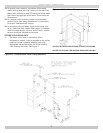
As An Option
The damper may be installed in any horizontal or
vertical position, closer to the fl ue outlet collar
preferred. Follow the diagrams - Figures 6, 7 and 8.
Install the vent damper to service only the single boiler
2.
for which it is intended. The damper position indicator
shall be in a visible location following installation.
Locate the damper so that it is accessible for servicing.
The damper must be in the open position when
3.
appliance main burners are operating.
The boiler is equipped with a factory wired harness
4.
that plugs into the vent damper. The thermostat
must be connected to the black wires marked 24 volt
thermostat on the boiler.
Vent pipe must be same size as the fl ue outlet collar.
5.
Slope pipe up from boiler to chimney not less than 1/4”
6.
per foot.
Run pipe as directly as possible with as few elbows as
7.
possible.
Do not connect to fi replace fl ue.
8.
End of vent pipe must be fl ush with inside face of
9.
chimney fl ue. Use a sealed-in thimble for the chimney
connection.
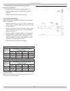
Horizontal run should not be longer than 3/4 the
10.
chimney height (HT) (Fig.5).
The sections of vent pipe should be fastened with sheet
metal screws to make the piping rigid. Horizontal portions
of the vent system must be supported to prevent sagging.
Use stovepipe wires every 5’ to support the pipe from above.
If the vent pipe must go through a crawl space, double wall
vent pipe should be used. Where vent pipe passes through a
combustible wall or partition, use a ventilated metal thimble.
The thimble should be 4 inches larger in diameter than the
vent pipe.
MINIMUM VENT PIPE CLEARANCE
Wood and other combustible materials must not be closer
than 6” from any surface of single wall metal vent pipe.
Listed Type B vent pipe or other listed venting systems shall
be installed in accordance with their listing.
REMOVING EXISTING BOILER FROM COMMON
VENTING SYSTEM
When an existing boiler is removed from a common venting
system, the common venting system is likely to be too large
for proper venting of the appliances remaining connected to
it.
At the time of removal of an existing boiler, the following steps
shall be followed with each appliance remaining connected
to the common venting system placed in operation, while
the other appliances remaining connected to the common
venting system are not in operation.
Seal any unused openings in the common venting
1.
system.
Visually inspect the venting system for proper size and
2.
horizontal pitch and determine there is no blockage or
restriction, leakage, corrosion and other defi ciencies
which could cause an unsafe condition.
Insofar as is practical, close all building doors and
3.
windows and all doors between the space in which the
appliances remaining connected to the common venting
system are located and other spaces of the building.
Turn on clothes dryers and any appliance not connected
to the common venting system. Turn on any exhaust
fans, such as range hoods and bathroom exhausts, so
they will operate at maximum speed. Do not operate a
summer exhaust fan. Close fi replace dampers.
Place in operation the appliance being inspected. Follow
4.
the lighting instructions. Adjust thermostat so appliance
will operate continuously.
Test for spillage at the draft hood relief opening after
5.
5 minutes of main burner operation. Use the fl ame of
a match or candle, or smoke from a cigarette, cigar or
pipe.