


5
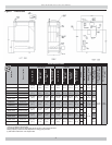
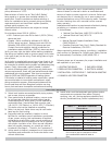
Net I=B=R steam Ratings shown are based on piping and
pickup allowance of 1.333.
Base selection of boiler size on "Net I=B=R Rating"
being equal to or greater than installed radiation in
square feet. Consult manufacturer before selecting a
boiler for installations having unusual piping and pickup
requirements,such as intermittent system operation,
exhaust piping systems, etc.
Specifi cations and dimensions are subject to change
without notice.
For elevations above 2000 ft. (600m):
USA - Reduce input rate 4% for each 1,000 ft (300m) •
above sea level.
Canada - Boiler certifi ed for altitudes of 0-2000 ft •
(610m) above sea level. Reduce input rate 10% for
altitudes 2000-4500 ft (610-1350) above sea level.
Contact Provincial authority having jurisdiction for
installations above 4500 feet (1350 m) above sea level.
BEFORE YOU START
Verify you have right size boiler before starting installation.
See rating and capacity table on previous page. Verify boiler
is for type of gas you are using. Check rating plate on right
side of boiler.
Verify boiler is supplied with correct type of gas, fresh air for
combustion, and suitable electrical supply. Also, boiler must
be connected to suitable venting system and adequate piping
system. Finally, thermostat, properly located, is needed
for control of heating system. If you have any doubts as to
various requirements, check with local authorities and obtain
professional help where needed. Take time to complete all
steps for SAFE and PROPER operation of heating system.
If this boiler is installed in building under construction, special
care must be taken to insure clean combustion air supply
during construction process. Airborne particulates such as
from drywall dust and from fi berglass insulation can clog
burner ports and cause incomplete combustion and sooting.
Boilers are designed for use in closed heating systems
where all steam is returned to boiler as condensate and
amount of make-up water required is minimal. Boilers are
not designed for or intended for use in open systems of
process applications using 100% make-up water. Damage
to boiler resulting from such use shall not be covered
under warranty.
Installation shall conform to requirements of authority having
jurisdiction or in absence of such requirements:
United States •
National Fuel Gas Code, ANSI Z223.1/NFPA 54. •
National Electrical Code, NFPA 70.•
Canada •
Natural Gas and Propane Installation Code, •
CAN/CSA B149.1.
Canadian Electrical Code, Part I, Safety Standard for •
Electrical Installations, CSA C22.1
Where required by authority having jurisdiction, installation
shall conform to Standard for Controls and Safety Devices
for Automatically Fired Boilers, ANSI/ASME CSD-1.
Following steps are all necessary for proper installation and
safe operation of your boiler.
1. LOCATING THE BOILER 5. GAS SUPPLY PIPING
2. FRESH AIR FOR COMBUSTION 6. ELECTRICAL WIRING
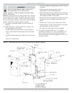
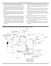
3. INSTALLATION - SYSTEM PIPING 7. CHECKING & ADJUSTING
4. CHIMNEY & VENT PIPE CONNECTION
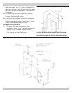
LOCATING THE BOILER
Select level location as centralized with piping system,
1.
and as near chimney as possible.
Place crated boiler at selected location, remove crate
2.
by pulling crate sides from top and bottom boards.
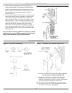
Combustible fl oors: When boiler is to be installed on
combustible fl oor, Special Base Plate must be used -
146-14-031 (2-6 Section) or 146-14-032 (7-9 Section).
This boiler must not be installed on carpeting.
Boiler is to be level. Metal shims may be used under
3.
base legs for fi nal leveling.
Equipment shall be installed in location in which
4.
facilities for ventilation permit satisfactory combustion
of gas, proper venting, and maintenance of ambient
temperature at safe limits under normal conditions of
use. Equipment shall be located so as not to interfere
with proper circulation of air. When normal infi ltration
does not provide necessary air, outside air shall be
introduced (See Page 6 - “Fresh Air for Combustion”).
Advise owner to keep air passages free of obstructions.
5.
Ventilating and combustion air must enter boiler room
without restrictions.
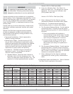
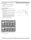
Table - 1 Minimum Clearance
Dimensions
Top 6" (16 cm)
Rear 6" (16 cm)
Control Side 7" (18 cm)
Opposite Side 6" (16 cm)
Front Alcove
Flue/Vent Connector 6" (16 cm)
Near Boiler Piping 1" (2.5 cm)
Unit must be set on concrete or other
non-combustible material base or
fl oor.
Install boiler such that automatic gas ignition system
6.
components are protected from water (dripping,
spraying, rain, etc.) during appliance operation and
service (condensate trap, control replacement, etc.).