


11
After it has been determined that each appliance
6.
remaining connected to the common venting system
properly vents when tested as outlined above, return
doors, windows, exhaust fans, fi replace dampers and
any other gas-burning appliance to their previous
conditions of use.
Any improper operation of the common venting system
7.
should be corrected so the installation conforms with
the National Fuel gas Code, ANSI Z223.1/NFPA 54,
and/or the Natural Gas and Propane Installation Code,
CAN/CSA B149.1. When re-sizing any portion of the
common venting system, the common venting system
should be re-sized to approach the minimum size
determined using the appropriate tables in Chapter 13
of the National Fuel Gas Code, ANSI Z223.1/NFPA 54,
and/or the Natural Gas and Propane Installation Code,
CAN/CSA B149.1.
Vent connectors serving appliances vented by natural
draft shall not be connected into any portion of mechanical
draft systems operating under positive pressure.
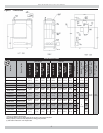
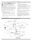
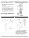
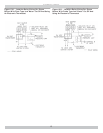
CHIMNEY AND VENT PIPE CONNECTION
Figure 5 - Typical Masonry Chimney Requirements
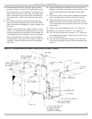
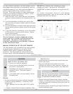
VENT DAMPER OPERATION
TYPICAL INSTALLATION FOR VENT DAMPER
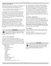
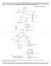
NOTE CAUTION AND FOOTNOTES
Install the vent damper to service only the single
1.
appliance for which it is intended. If improperly
installed, a hazardous condition, such as an explosion
or carbon monoxide poisoning, could result.
Do not install the vent damper on vent pipe curve.
2.
Do not run wires near high temperature surfaces.
3.
Use stand-off brackets if necessary.
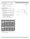
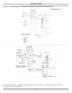
Figure 6 - Horizontal Installation
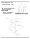
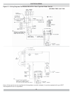
Figure 7 - Alternate Vent Damper Installation