


Page 6
freeze on the walls or on overhangs (under eaves). The
vent outlet should not discharge flue products on a
sidewalk, patio or other walkway where the condensate
could cause the surface to become slippery.
Do not install the unit so that the products of
combustion will be allowed to accumulate within a
confined space and recirculate.
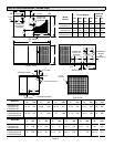
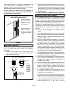
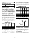
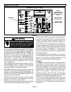
Figure 3
Minimum Clearance
AboveVent Hood:
Distance fromTop
ofVent Hood
toTop of Unit
Minimum Clearance
BelowVent Hood:
Distance from Bottom
ofVent Hood to Base
of Unit
Minimum Clearances to Combustible Materials
Above and Below Vent Hood
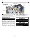
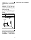
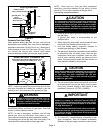
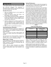
Vent Hood Installation
The vent hood, screen and screws are shipped inside the
unit in the plastic bag which contains the installation
instructions.
1 − Insert the vent screen into the vent tube Once
inserted, the screen should be flush with the end of the
tube as shown in figure 4.
Vent Hood Installation
Figure 4
Screen
Vent Hood
TopView
Slotted side of
vent hood faces
condenser coil.
Screen
VentTube
FrontView
Screen is pre−formed
VentTube
NOTE −
Screws
should pass
through
sides of
screen to
hold screen
in place.
2 − Position the vent hood over the vent tube so that the
slotted side of the hood faces the condenser coil. Use
the four sheet metal screws (provided) to secure the
vent hood to the vent tube. The screws should pass
through the sides of the screen in order to hold the
screen in place.
The vent hood must be installed prior to unit start−up.
Existing Common Vent Systems
If this packaged outdoor unit is replacing an existing
indoor furnace that is being removed from a venting
system commonly run with a water heater or other gas
appliance, the venting system is likely to be too large to
properly vent the remaining attached appliance(s).
Conduct the following test while the water heater is
operating and the other gas appliances (which are not
operating) remain connected to the common venting
system.
1 − Seal any unused openings in the common venting
system.
2 − Inspect the venting system for proper size and horizontal
pitch. Determine that there is no blockage, restriction,
leakage, corrosion, or other deficiencies which could
cause an unsafe condition.
3 − Close all building doors and windows and all doors
between the space in which the appliances remaining
connected to the common venting system are located
and other spaces of the building. Turn on clothes
dryers and any appliances not connected to the
common venting system. Turn on any exhaust fans,
such as range hoods and bathroom exhausts, so they
will operate at maximum speed. Do not operate a
summer exhaust fan. Close fireplace dampers.
4 − Follow the lighting instructions. Turn on the appliance
that is being inspected. Adjust the thermostat so that
the appliance operates continuously.
5 − After the burner has operated for 5 minutes, test for
leaks of flue gases at the draft hood relief opening. Use
the flame of a match or candle, or smoke from a
cigarette, cigar, or pipe.
6 − After determining that each appliance connected to the
common venting system is venting properly, (step 3)
return all doors, windows, exhaust fans, fireplace
dampers, and any other gas−burning appliances to
their previous mode of operation.
7 − If a venting problem is found during any of the
preceding tests, the common venting system must be
modified to correct the problem.
If necessary, you must resize the common venting
system to the minimum vent pipe size determined by
using the appropriate tables in Appendix G. (These are
in the current standards of the National Fuel Gas Code
ANSI-Z223.1/NFPA 54 in the USA, and the