


Page 17
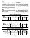
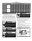
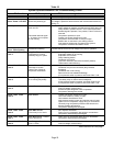
Table 8
Normal Operating Pressures
80F db / 67F wb RETURN AIR Air Temperature Entering Outdoor Coil (F)
UNIT PRESSURE 65 70 75 80 82 85 90 95 100 105 110 115
15GCSX−24
Suction
142 143 144 146 146 147 148 149 150 151 152 153
15GCSX−30 134 136 138 140 141 142 144 146 148 149 151 152
15GCSX−36 143 144 146 147 148 149 151 152 155 155 157 157
15GCSX−42 140 140 140 141 141 141 142 142 143 144 145 147
15GCSX−48 133 134 136 137 138 139 139 140 141 142 144 145
15GCSX−60 134 136 138 140 141 142 144 145 147 148 150 151
15GCSX−24
Liquid
219 242 264 287 296 310 333 355 379 398 430 457
15GCSX−30 232 255 277 300 309 323 345 368 390 408 440 470
15GCSX−36 244 268 292 316 326 340 363 369 410 429 461 493
15GCSX−42 225 247 269 291 300 314 337 357 383 402 434 457
15GCSX−48 236 256 277 297 305 320 344 370 393 412 449 480
15GCSX−60 246 269 291 314 323 337 360 385 407 424 457 484
Heating Start−Up
Pre−Start Check List:
1 − Check the type of gas being supplied. Be sure it is the
same as listed on the unit nameplate.
2 − Make sure the vent hood has been properly installed.
FOR YOUR SAFETY READ BEFORE LIGHTING
BEFORE LIGHTING smell all around the appliance area
for gas. Be sure to smell around the base of the unit
because some gas is heavier than air and will settle down
low.
Electric shock hazard. Can cause injury
or death. Do not use this unit if any part
has been under water. Immediately call a
qualified service technician to inspect
the unit and to replace any part of the con-
trol system and any gas control which
has been under water.
WARNING
!
WARNING
Danger of explosion and fire. Can cause
injury or product or property damage. You
must follow these instructions exactly.
!
Danger of explosion. Can cause injury or
product or property damage. If overheating
occurs or if gas supply fails to shut off, shut
off the manual gas valve to the appliance
before shutting off electrical supply.
WARNING
!
Electric shock hazard. Can cause injury or
death. Before attempting to perform any
service or maintenance, turn the electrical
power to unit OFF at disconnect switch(es).
Unit may have multiple power supplies.
WARNING
!
Use only your hand to turn the gas valve knob. Never use
tools. If the knob will not move by hand, do not try to repair
the gas valve. Call a qualified service technician. Force or
attempted repair may result in a fire or explosion.
This furnace is equipped with a direct ignition control. Do
not attempt to manually light the burners.
1 − Turn off electrical power to unit.
2 − Set thermostat to lowest setting.
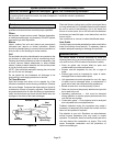
3 − Turn the gas valve knob to the ON position. Refer to
figure 13.
4 − Turn on electrical power to unit.
5 − Set room thermostat to desired temperature. (If
thermostat setpoint temperature is above room
temperature after the pre−purge time expires, main
burners will light).
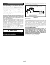
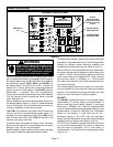
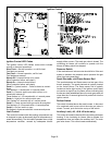
Figure 13
Honeywell VR8205 Series Gas Valve
GAS VALVE SHOWN IN OFF POSITION
OUTLET
(MANIFOLD)
PRESSURE
TAP
HIGH FIRE
ADJUSTING SCREW
(under cap)
INLET PRESSURE TAP
LOW FIRE
ADJUSTING SCREW
(under cap)