


Page 15
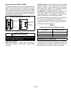
COOL
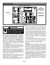
The COOL jumper is used to determine the CFM during
cooling operation. This jumper selection is activated for
cooling when Y1 is energized.
The blower motor runs at 80 percent of the selected air
flow for the first 7−1/2 minutes of each cooling demand.
This feature allows for greater humidity removal and
saves energy.
In the cooling mode, the blower control delays blower
operation for 5 seconds after the compressor starts. The
blower continues to operate for 90 seconds after the
compressor is de−energized.
HEAT
The HEAT jumper is used to determine CFM during gas
heat operation only. These jumper selections are activated
only when W1 is energized.
In the heating mode, the blower control delays blower
operation for 30 seconds after the flame is established. The
blower continues to operate for 90 seconds after the gas
valve is de−energized.
CONTINUOUS FAN
When the thermostat is set for Continuous Fan" operation
and there is no demand for heating or cooling, the blower
control will provide 50 percent of the COOL CFM selected.
NOTE − With the proper thermostat and subbase,
continuous blower operation is possible by closing the R to
G circuit. Cooling blower delay is also functional in this
mode.
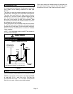
DEHUMIDIFICATION
The blower control includes an HUM terminal which
provides for connection of a humidistat. The JV1 resistor on
the blower control must be cut to activate the HUM
terminal. The humidistat must be wired to open on humidity
rise. When the dehumidification circuit is used, the variable
speed motor will reduce the selected air flow rate by 25
percent when humidity levels are high. An LED (D1) lights
when the blower is operating in the dehumidification mode.
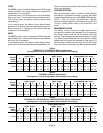
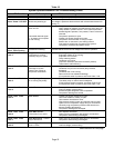
Table 4
15GCSXAV−24, 15GCSXAV−30 Blower Performance
0 through 0.80 in. w.g. (0 through 200 Pa) External Static Pressure Range
ADJUST
Jumper
Setting
Jumper Speed Positions
COOL" Speed HEAT" Speed CONTINUOUS FAN" Speed
A B C D A B C D A B C D
cfm L/s cfm L/s cfm L/s cfm L/s cfm L/s cfm L/s cfm L/s cfm L/s cfm L/s cfm L/s cfm L/s cfm L/s
+ 1150 545 920 435 690 325 1035 490 1265 595 1150 545 1035 490 920 435 575 270 460 215 345 165 520 245
NORM 1000 470 800 380 600 285 900 425 1100 520 1000 470 900 425 800 380 500 235 400 190 300 140 450 210
− 850 400 680 320 510 240 765 360 935 440 850 400 765 360 680 320 425 200 340 160 300 140 385 180
Table 5
15GCSXAV−36 Blower Performance
0 through 0.80 in. w.g. (0 through 200 Pa) External Static Pressure Range
ADJUST
Jumper
Setting
Jumper Speed Positions
COOL" Speed HEAT" Speed CONTINUOUS FAN" Speed
A B C D A B C D A B C D
cfm L/s cfm L/s cfm L/s cfm L/s cfm L/s cfm L/s cfm L/s cfm L/s cfm L/s cfm L/s cfm L/s cfm L/s
+ 1380 650 1150 545 920 435 1265 575 1555 735 1265 595 1150 545 1035 490 690 325 575 270 460 215 635 300
NORM 1200 565 1000 470 800 380 1100 520 1350 635 1100 520 1000 470 900 425 600 285 500 235 400 190 550 260
− 1020 480 850 400 680 320 935 440 1150 540 935 440 850 400 765 360 510 240 425 200 350 165 470 220
Table 6
15GCSXAV−42, 15GCSX(A,B)V−48, 15GCSX(A,B)V−60, Blower Performance
0 through 0.80 in. w.g. (0 through 200 Pa) External Static Pressure Range
ADJUST"
Jumper
Setting
Jumper Speed Positions
COOL" Speed HEAT" Speed CONTINUOUS FAN" Speed
A B C D A B C D A B C D
cfm L/s cfm L/s cfm L/s cfm L/s cfm L/s cfm L/s cfm L/s cfm L/s cfm L/s cfm L/s cfm L/s cfm L/s
+ 2070 975 1840 870 1610 760 1380 650 2015 950 1900 895 1555 735 1325 625 1035 490 920 435 805 380 690 325
NORM 1800 850 1600 755 1400 660 1200 565 1750 825 1650 780 1350 635 1150 545 900 425 800 380 700 330 600 285
− 1530 720 1360 640 1190 560 1020 480 1490 700 1405 660 1150 540 980 460 765 360 680 320 595 280 510 240