


Page 14
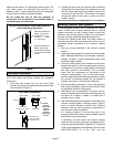
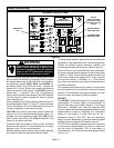
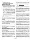
Blower Control (A54)
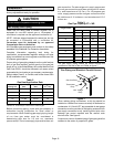
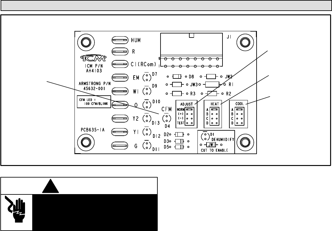
BLOWER CONTROL (A54)
16−PIN PLUG
(BOARD TO MOTOR)
ADJUST
SELECTOR PINS
(Setting affects both
heating and cooling
modes)
DIAGNOSTIC
LED
HEATING SPEED
SELECTOR PINS
COOLING SPEED
SELECTOR PINS
Figure 12
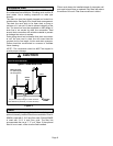
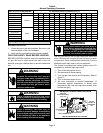
Electric shock hazard. Can cause injury or
death. Before attempting to perform any
service or maintenance, turn the electrical
power to unit OFF at disconnect switch(es).
Unit may have multiple power supplies.
WARNING
!
15GCSX units are equipped with a variable speed motor
that is capable of maintaining a specified CFM throughout
the external static range. A particular CFM can be obtained
by positioning jumpers (COOL, HEAT, and ADJUST) on
the blower control. The HEAT and COOL jumpers are
labeled A, B, C and D. Each of the numbers corresponds
with an air volume (CFM) setting. The ADJUST jumper is
labeled Test, −, +, and Norm. The + and − pin settings are
used to add or subtract a percentage of the CFM selected.
The Test jumper is used to operate the motor in the test
mode. See figure 12.
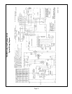
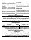
Factory settings for the blower speed jumpers are given in
the wiring diagram in figure 11. Figure 12 shows the blower
control. Use tables 4, 5 and 6 to determine the correct air
volume for operation in heat and cool mode.
The CFM LED located on the blower control flashes one
time per 100 cfm to indicate selected blower speed. For
example, if the unit is operating at 1000 CFM, CFM LED will
flash 10 times. If the CFM is 1150, CFM LED will flash 11 full
times plus one fast or half flash.
At times the light may appear to flicker or glow. This takes
place when the control is communicating with the motor
between cycles. This is normal operation.
Read through the jumper settings section before adjusting
the jumper to obtain the appropriate blower speed.
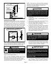
To change jumper positions, gently pull the jumper off the pins
and place it on the desired set of pins. The following section
outlines the different jumper selections available and
conditions associated with each one. Refer to figure 12.
After the CFM for each application has been determined,
the jumper settings must be adjusted to reflect those given
in tables 4, 5 and 6. From the tables, determine which row
most closely matches the desired CFM. Once a specific
row has been chosen (+, NORMAL, or −), CFM volumes
from other rows cannot be used. Below are descriptions of
the jumper selections.
The variable speed motor slowly ramps up to and down
from the selected air flow during both cooling and heating
demand. This minimizes noise and eliminates the initial
blast of air when the blower is initially energized.
ADJUST
The ADJUST pins allow the motor to run at normal speed,
approximately 15 percent higher, or approximately 15
percent lower than normal speed. Tables 4, 5 and 6 give
three rows (+, NORMAL, and −) with their respective CFM
volumes. Notice that the normal adjustment setting for heat
speed position C in table 4 is 900 CFM. The + adjustment
setting for that position is 1035 CFM and for the −
adjustment setting is 765 CFM. After the adjustment
setting has been determined, choose the remaining speed
settings from those offered in the table in that row.
The TEST pin is available to bypass the blower control and
run the motor at approximately 70 percent to make sure
that the motor is operational. This is used mainly in
troubleshooting. The G terminal must be energized for the
motor to run.