


Page 18
To Shut Down:
1 − Turn off electric power to unit.
2 − Turn the gas valve knob to the OFF position.
Post Start−up Check List (Gas)
After the control circuit has been energized and the heating
section is operating, make the following checks:
1 − Use soap solution to check for gas leaks in the unit
piping as well as the supply piping.
2 − Check for correct manifold gas pressures. See
Manifold Gas Pressure Adjustment."
3 − Check the supply gas pressure. It must be within the
limits shown on rating nameplate. Supply pressure
should be checked with all gas appliances in the
building at full fire. At no time should the supply gas
pressure exceed 10.5 inches w.c., nor drop below 5.0
inches w.c. for natural gas units. For propane gas,
supply gas pressure should not drop below 11 inches
w.c. If gas pressure is outside these limits, contact
your gas supplier for corrective action.
4 − Adjust temperature rise to the range specified on the
rating plate.
Checking and Adjusting Gas Input
NOTE − Units must be converted for use with LP/propane
gas. Conversion kit is ordered separately. Conversion
must be performed by an approved licensed pipe fitter
or technician.
The minimum permissible gas supply pressure is 5.0
inches W.C. for natural gas or 11.0 inches W.C. for
LP/propane gas. The maximum inlet gas supply pressure
is 10.5 inches W.C. for natural gas and 13.0 inches W.C. for
LP/propane gas. Gas input must never exceed the input
capacity shown on the rating plate.
Units fueled by natural gas are rated for manifold pressures
of 2.0 inches W.C. for first stage and 3.5 inches W.C. for
second stage.
Units fueled by LP/propane gas are rated for manifold
pressures of 5.6 inches W.C. for first stage and 10.0 inches
W.C. for second stage.
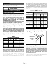
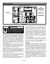
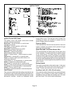
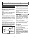
Measure manifold pressure: Shut off gas supply to the
unit. Remove plug from pressure tap. See figure 13.
Connect manometer or gauge to the proper pressure tap,
then turn on the gas supply.
The Honeywell VR8205 gas valve has separate adjusting
screws for first stage (LO) and second stage (HI). The
adjusting screws are positioned on either side of the
barbed fitting. Turn the adjusting screws clockwise to
increase pressure and input; turn counterclockwise to
decrease pressure and input. The pressure regulator
adjustment is sensitive. One turn of the adjusting screw
results in a large change in manifold pressure.
Final first−stage and second−stage manifold pressures
must be within the allowable rangers for the gas being
used.
For Natural Gas: Check the furnace rate by observing gas
meter, making sure all other gas appliances are turned off.
The test hand on the meter should be timed for at least one
revolution. Note the number of seconds for one revolution.
BTU/HR = Cubic Feet Per Revolution X 3600 X Heating Value
INPUT No. Seconds Per Revolution
The heating value of your gas can be obtained from your
local utility.
For LP/Propane Gas: If a gas meter is available, check the
input rate as described in the section above. Heating value
of propane gas is available from propane supplier.
Otherwise, the only check for the output rate is to properly
adjust the manifold pressure using a manometer. Typical
manifold setpoint for installations at altitudes from 0 to 4500
feet above sea level is 10.0 inches W.C.
High Altitude Information
Ratings shown on the rating plate for elevations up to 4,500
feet. For elevations above 4,500 feet, ratings should be
reduced at a rate of four percent for each 1,000 feet above
sea level. See National Fuel Gas Code Z223.1 (latest
edition) or the requirements of the CSA B149 installation
codes.
Heating Sequence of Operation
When the thermostat calls for heating, W1 is energized.
NOTE − The ignition control ignores a call for second−stage
heat until first−stage heat has been established.
The ignition control checks high temperature limit and roll
out switches to make sure they are closed. The control then
verifies that the pressure switch is open. If the pressure
switch is closed, the control will flash code 3 on the LED
and will wait indefinitely for the pressure switch to open. If
the pressure switch is open, the control proceeds to the
15−second pre−purge.
The ignition control energizes the combustion air inducer
on high speed, flashes a code 3 on the LED, and waits for
the pressure switch to close.
When the pressure switch has closed, the LED code 3 flash
stops and the control begins the 15−second pre−purge
period. When the pre−purge time has expired, the control
begins the ignition trial.
The ignition control energizes the gas valve and spark. The
control ignores the flame sense signal for the first two
seconds of the ignition trial. If the flame is established
within 10 seconds, the control de−energizes the spark. If
flame is not established within 10 seconds, the gas valve
and spark are de−energized and the ignition control
initiates a 30−second inter−purge sequence.
Approximately 30 seconds after the flame has been
established, the circulating air blower starts and the
combustion air inducer is switched to low speed. The
ignition control inputs are continuously monitored to
ensure that limit switch(es), roll out switch and pressure
switch are all closed, and that the flame remains
established and heating demand is present. First−stage
gas valve, low−speed combustion air inducer and