


Page 10
Compressors
Units are shipped with the compressor mountings
factory−adjusted and ready for operation.
CAUTION
Do not loosen compressor mounting bolts.
Gas Supply and Piping
Check the unit rating plate to confirm whether unit is
equipped for use with natural gas or LP/propane. If
conversion is required use the approved conversion kit.
NOTE − Units are shipped equipped for natural gas, but can
be converted to LP/propane with a conversion kit.
Conversion must be performed by an approved
licensed pipe fitter or technician.
All LP/propane gas equipment must conform to the safety
standards of the National Fire Protection Association.
Complete information regarding tank sizing for
vaporization, recommended regulator settings, and pipe
sizing is available from most regulator manufacturers and
LP/propane gas suppliers.
Proper sizing of gas piping depends on the cubic feet per
hour of gas flow required, specific gravity of the gas and
length of run. In the United States, the current National Fuel
Gas Code Z223.1 should be followed in all cases unless
superseded by local codes or gas company requirements.
Refer to tables 2 and 3. In Canada, refer to the current CSA
B.149 installation codes.
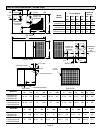
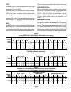
Table 2
Gas Heat Application Data
Unit
Heating Size
Input Rating
(Btu)
Output Rating
(Btu)
Gas Capacity*
(FT
3
/ HR)
68 67,500 54,000 63
83 82,500 66,000 77
90 90,000 72,000 84
110 110,000 88,000 102
138 137,500 110,000 128
*Based on 1075 Btu per cubic foot of natural gas.
Before connecting piping, check with gas company or
authorities having jurisdiction for local codes or
requirements. When installing gas supply piping, length
of run from gas meter must be considered in
determining pipe size for 0.5 inch w.c. maximum
pressure drop. Do not use supply pipe smaller than unit
gas connection. For natural gas unit, supply pressure at
the unit gas connection must be a minimum of 5 inches
w.c. and a maximum of 10.5 w.c. For LP/propane gas
units, supply pressure at the unit gas connection must
be a minimum of 11 inches w.c. and a maximum of 13.0
inches w.c.
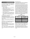
Table 3
Gas Pipe Capacity−FT
3
/ HR
Length in Feet
Nominal Iron Pipe Size (inches)
1/2 in. 3/4 in. 1 in. 1−1/4 in.
10 132 278 520 1050
20 92 190 350 730
30 73 152 285 590
40 63 130 245 500
50 56 115 215 440
60 50 105 195 400
70 46 96 180 370
80 43 90 170 350
90 40 84 160 320
100 38 79 150 305
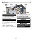
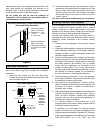
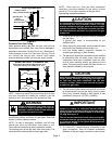
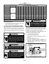
The gas supply piping should be routed through the
grommet on the side of the unit. Refer to figure 7.
Figure 7
Gas Piping and Electrical Conduit Access
Gas Line Entry
Thermostat
Entry
Line Voltage
Entry
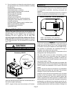
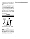
When making piping connections, a drip leg should be
installed on vertical runs to serve as a trap for sediment or
condensate. A 1/8 inch N.P.T. tap accessible for test gauge
connection must be provided in field piping upstream from
gas supply connection to unit. Install a ground joint union
between gas control manifold and the manual main
shut−off valve. See figure 8.
Compounds used on threaded joints of gas piping shall be
resistant to the action of propane/LP gases.