


Page 44
12− If the appliance will not operate, follow the instructions
Turning Off Gas to Unit" and call your service techni-
cian or gas supplier.
Turning Off Gas to Unit
1 − Set the thermostat to the lowest setting.
2 − Turn off all electrical power to the unit if service is to be
performed.
3 − Remove the upper access panel.
4 − White Rodgers 36E Gas Valve − Move gas valve
switch to OFF.
Honeywell VR8205 Gas Valve − Move switch on gas
valve clockwise to OFF. Do not force.
5 − Replace the upper access panel.
Gas Pressure Adjustment
Gas Flow (Approximate)
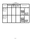
1 − Operate unit at least 15 minutes before checking gas
flow. Determine the time in seconds for one revolu-
tions of gas through the meter. A portable LP gas me-
ter (17Y44) is available for LP applications.
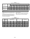
2 − Compare the number of seconds and the gas meter
size in table 12 to determine the gas flow rate. Multiply
the gas flow rate by the heating value to determine the
unit input rate. If manifold pressure is correct and the
unit input rate is incorrect, check gas orifices for proper
size and restriction.
3 − Remove temporary gas meter if installed.
NOTE − To obtain accurate reading, shut off all other gas
appliances connected to meter.
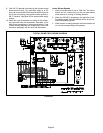
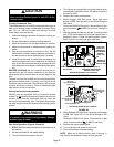
Supply Pressure Measurement
A threaded plug on the inlet side of the gas valve provides
access to the supply pressure tap. Remove the threaded
plug, install a field−provided barbed fitting and connect a
manometer to measure supply pressure. Replace the
threaded plug after measurements have been taken.
Manifold Pressure Measurement
To correctly measure manifold pressure, the differential
pressure between the positive gas manifold and the nega-
tive burner box must be considered. Use pressure test
adapter kit (available as Lennox part 10L34) to assist in
measurement.
1 − Remove the threaded plug from the outlet side of the
gas valve and install a field−provided barbed fitting.
Connect test gauge +" connection to barbed fitting to
measure manifold pressure.
2 − Tee into the gas valve regulator vent hose and connect
test gauge −" connection.
TABLE 12
Gas Flow Rate (Ft.
3
/Hr.)
Seconds for 1
Revolution
Gas Meter Size
1/2 cu ft Dial 1 cu ft Dial
10 180 360
12 150 300
14 129 257
16 113 225
18 100 200
20 90 180
22 82 164
24 75 150
26 69 138
28 64 129
30 60 120
32 56 113
34 53 106
36 50 100
38 47 95
40 45 90
42 43 86
44 41 82
46 39 78
48 38 75
50 36 72
52 35 69
54 33 67
56 32 64
58 31 62
60 30 60
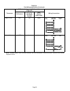
3 − Start unit on low heat (68% rate) and allow 5 minutes
for unit to reach steady state.
4 − While waiting for the unit to stabilize, notice the flame.
Flame should be stable and should not lift from burner.
Natural gas should burn blue.
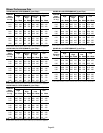
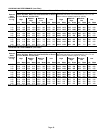
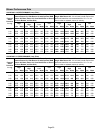
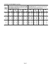
5 − After allowing unit to stabilize for 5 minutes, record
manifold pressure and compare to value given in table
13.
6 − Repeat steps 3, 4 and 5 on high heat.
NOTE − Shut unit off and remove manometer as soon as an
accurate reading has been obtained. Take care to remove
barbed fitting and replace threaded plug.
CAUTION
Do not attempt to make adjustments to the gas valve.