


Page 24
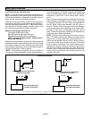
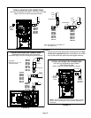
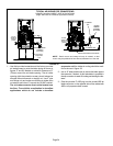
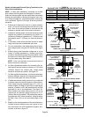
TYPICAL AIR INTAKE PIPE CONNECTIONS
DOWNFLOW NON−DIRECT VENT APPLICATIONS
(Right−Hand Exit in Downflow Applications Shown)
FIGURE 28
PLUG
(Must be
glued in
place)
6 in. Max.
PLUG
(Must be
glued in
place)
Downflow Additive Flloor Base
18 in.
Downflow
Evaporator
Coil
2"
2" SWEEP
ELL
2" SWEEP ELL
INTAKE DEBRIS
SCREEN
(Provided)
INTAKE
DEBRIS
SCREEN
(Provided)
NOTE − Debris screen and sweep ell may be rotated, so that
screen may be positioned to face forward, backward or to the side.
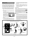
1 − Use field−provided materials and the factory−provided
air intake screen to route the intake piping as shown in
figures 27 and 28. Maintain a minimum clearance of 3"
(76mm) around the air intake opening. The air intake
opening (with the protective screen) should always be
directed either downward or straight out. Use 2" pipe
and fittings only and make sure that the air intake does
not extend more than 6" beyond the G61MP cabinet.
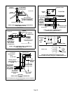
The air intake connector must not be located near
the floor. To avoid this complication in downflow
applications which do not include a downflow
evaporator coil, the intake air routing should be modi-
fied as shown in figure 28.
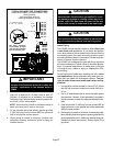
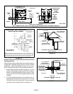
2 − Use a #7 sheet metal screw to secure the intake pipe to
the connector, if desired. A pilot indentation is provided in
the slip connector to assist in locating and starting the fas-
tener.
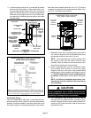
3 − Glue the provided 2" ABS plug into the unused ABS air
intake connector on the opposite side of the cabinet with
ABS or all purpose solvent cement.