


Page 32
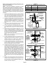
NOTE − The condensate trap drain stubs (both sides)
have an outer diameter which will accept a standard
3/4" PVC coupling. The inner diameter of each stub
will accept standard 1/2" diameter PVC pipe.
NOTE − Vinyl tubing may be used for condensate
drain. Tubing must be 1−1/4" OD X 1" ID and should be
attached to the drain stubs on the trap using a hose
clamp.
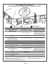
4 − Glue the field−provided drain line to the tee. Route the
drain line to an open drain. As an alternate, clear vinyl
tubing may be used to drain condensate away from
the trap. Secure the vinyl tubing to the drain stubs on
the trap using a hose clamp. Do not overtighten the
hose clamp.
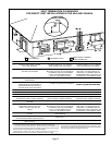
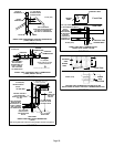
Condensate line must be sloped downward away from
condensate trap to drain. If drain level is above con-
densate trap, condensate pump must be used. Con-
densate drain line should be routed within the condi-
tioned space to avoid freezing of condensate and
blockage of drain line. If this is not possible, a heat
cable kit may be used on the condensate trap and line.
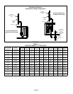
Heating cable kit is available from Lennox in various
lengths; 6 ft. (1.8m) − kit no. 26K68; 24 ft. (7.3m) − kit
no. 26K69; and 50 ft. (15.2m) − kit no. 26K70.
CAUTION
Do not use copper tubing or existing copper
condensate lines for drain line.
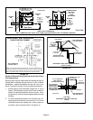
5 − If unit will be started immediately upon completion of
installation, prime trap per procedure outlined in Unit
Start−Up section.
6 − Glue the provided cap onto the unused condensate
drain line stub.
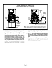
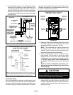
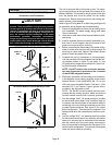
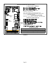
FIGURE 45
CONDENSATE ASSEMBLY
COUPLING
CAP
CONDENSATE TRAP
NIPPLE
NIPPLE
TEE
VENT
CLEAN−OUT ACCESS
(both sides)
HI/LO SCREWS
(DO NOT use power
driver. Hand−tighten
using screw driver.)
SCREW
O−RINGS
NOTE − Use screws to secure condensate trap to cabinet. DO
NOT apply glue to this joint. All other joints must be glued.