


Page 12
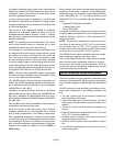
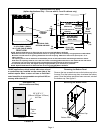
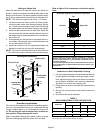
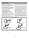
Setting an Upflow Unit
When the side return air inlets are used in an upflow ap-
plication, it may be necessary to install leveling bolts on the
bottom of the furnace. Use field−supplied corrosion−resist-
ant 5/16 inch machine bolts (4) and nuts (8). See figure 12.
NOTE − The maximum length of the bolt is 1−1/2 inches.
1 − Lie the furnace on its back and drill a 5/16 inch diame-
ter hole in each corner of the furnace’s bottom. See fig-
ure 12 for the correct location of the holes. Drill through
the bottom panel and the bottom flange of the cabinet.
2 − Install one bolt and two nuts into each hole. Screw the
first nut onto a bolt and then insert the bolt into a hole. A
flat washer may be added between the nut and the bot-
tom of the unit.
3 − Screw another nut onto the bolt on the inside of the fur-
nace base. A flat washer may be added between the
nut and the bottom of the unit.
4 − Adjust the outside nut to the appropriate height and
tighten the inside nut to secure the arrangement.
NOTE − The unit may be tilted back−to−front a maximum of
1". This will ensure proper draining of the heat exchanger.
FIGURE 12
1−3/4
(44)
1−3/4
(44)
3/8
(10)
1−3/4 (44)
3/8
(10)
3/8
(10)
3/8
(10)
1−3/4
(44)
Leveling Bolt Installation
Leveling Bolt
Locations
Leveling Bolt
Locations
Inches (mm)
Furnace Front
Furnace
Bottom
Downflow Applications
The unit may be installed three ways in downflow applica-
tions: on non−combustible flooring, on combustible flooring
using an additive base, or on a reverse−flow cooling cabi-
net. Do not drag the unit across the floor in the down-
flow position. Flange damage will result.
After unit has been properly set in place, position provided
logo over existing logo and affix sticker on front panel.
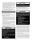
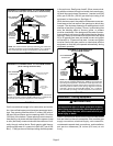
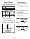
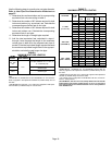
Refer to figure 13 for clearances in downflow applica-
tions.
Downflow Application Installation Clearances
Top
Bottom
Left Side
Right Side
Top 0
*Front 0
Back 0
Sides 0†
Vent 0
Floor NC‡
*Front clearance in alcove installation must be 24 in. (610 mm).
Maintain a minimum of 24 in. (610 mm) for front service access.
†Allow proper clearances to accommodate condensate trap and
vent pipe installation.
‡The furnace may be installed on a combustible wood floor if an op-
tional additive base is installed between the furnace and the com-
bustible floor.
FIGURE 13
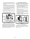
Installation on Non−Combustible Flooring
1 − Cut floor opening keeping in mind clearances listed on
unit rating plate. Also keep in mind gas supply connec-
tions, electrical supply, flue and air intake connections
and sufficient installation and servicing clearances.
See table 1 for correct floor opening size.
2 − Flange warm air plenum and lower the plenum into the
opening.
3 − Set the unit over the plenum and seal the plenum to
the unit.
4 − Ensure that the seal is adequate.
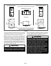
TABLE 1
NON−COMBUSTIBLE FLOOR OPENING SIZE
Model No.
Front to Rear Side to Side
in. mm in. mm
B Cabinet (17.5") 19 − 3/4 502 16 − 5/8 422
C Cabinet (21") 19 − 3/4 502 20−1/8 511
D Cabinet (24.5") 19 − 3/4 502 23 − 5/8 600
NOTE − Floor opening dimensions listed are 1/4 inch (6 mm) larger than
the unit opening. See dimension drawing on page 2.