


Page 6
General
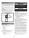
WARNING
Product contains fiberglass wool.
Disturbing the insulation in this product during
installation, maintenance, or repair will expose you
to fiberglass wool. Breathing this may cause lung
cancer. (Fiberglass wool is known to the State of Cal-
ifornia to cause cancer.)
Fiberglass wool may also cause respiratory, skin,
and eye irritation.
To reduce exposure to this substance or for further
information, consult material safety data sheets
available from address shown below, or contact your
supervisor.
Lennox Industries Inc.
P.O. Box 799900
Dallas, TX 75379−9900
CAUTION
SLP98DFV unit should not be installed in areas nor-
mally subject to freezing temperatures.
These instructions are intended as a general guide and do
not supersede local codes in any way. Consult authorities
having jurisdiction before installation.
In addition to the requirements outlined previously, the fol-
lowing general recommendations must be considered
when installing a SLP98DFV furnace:
• Place the furnace as close to the center of the air dis-
tribution system as possible. The furnace should also be
located close to the chimney or vent termination point.
• When the furnace is installed in an attic or other insu-
lated space, keep insulation away from the furnace.
• When the furnace is installed in an unconditioned
space, consider provisions required to prevent freezing
of condensate drain system.
Installation − Setting Equipment
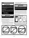
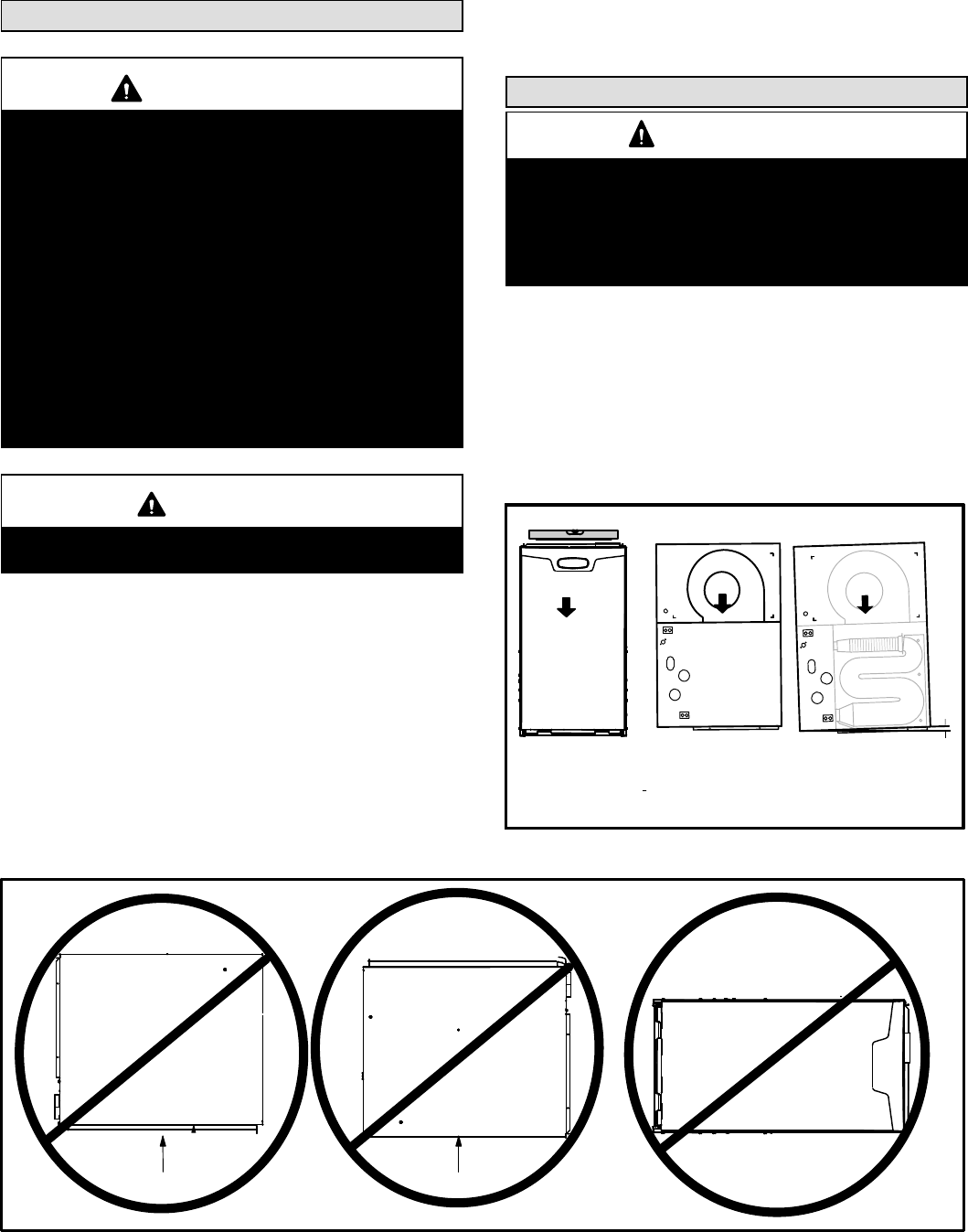
WARNING
Do not install the furnace on its front, back or in the
horizontal position. See figure 5. Do not connect the
return air ducts to the back of the furnace. Doing so
will adversely affect the operation of the safety con-
trol devices, which could result in personal injury or
death.
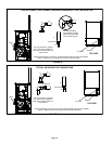
Select a location that allows for the required clearances
that are listed on the unit nameplate. Also consider gas
supply connections, electrical supply, vent connection,
condensate trap and drain connections, and installation
and service clearances [24 inches (610 mm) at unit
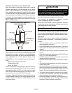
front]. The unit must be level from side to side. Unit may
be positioned from level to 1/2" toward the front to aid in
draining. See figure 4.
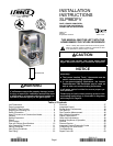
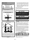
FIGURE 4
SETTING EQUIPMENT
FRONT VIEW SIDE VIEW
AIR FLOW
AIR FLOW
1/2"
max.
AIR FLOW
SIDE VIEW
Unit must be level side−to−side. Unit may be positioned
from level to 1/2" toward the front to aid in draining.
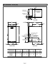
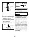
FIGURE 5
Front
Back
Horizontal
NOTE − Do not install the furnace on its front, back or in the horizontal position.