


Page 23
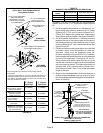
Condensate Piping
This unit is designed for either right- or left-side exit of con-
densate piping. Refer to figure 32 for condensate trap loca-
tions.
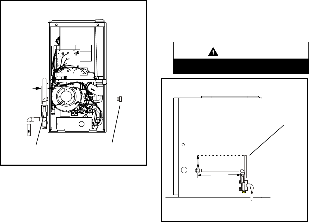
NOTE − If necessary the condensate trap may be installed
up to 5 feet away from the furnace. Piping from furnace
must slope down a minimum of 1/4" per ft. toward trap.
NOTE − Vinyl tubing may be used for condensate drain.
Tubing must be 1−1/4" OD X 1" ID and should be
attached to the drain on the trap using a hose clamp.
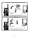
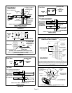
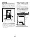
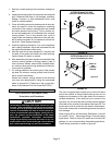
FIGURE 32
CONDENSATE TRAP AND PLUG LOCATION
(shown with left side exit of condensation)
1−1/2 in.
Trap
(same other right side)
Plug
(same on left side)
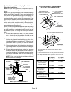
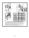
1 − Determine which side condensate piping will exit the
unit, location of trap, field−provided fittings and length of
PVC pipe required to reach available drain.
2 − Remove plug (figure 32) from the cold end header box
at the appropriate location on the side of the unit. Install
1/2 NPT male field provided fitting into cold end head-
er box. Do Not Over Tighten. Use teflon tape or ap-
propriate pipe dope.
3 − Install drain trap using appropriate PVC fittings, glue
all joints. Glue the provided drain trap as shown in fig-
ure 34. Route the condensate line to an open drain.
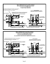
4 − If unit will be started immediately upon completion of
installation, prime trap per procedure outlined in Unit
Start−Up section.
Condensate line must be sloped downward away from
condensate trap to drain. If drain level is above con-
densate trap, condensate pump must be used. Con-
densate drain line should be routed within the condi-
tioned space to avoid freezing of condensate and
blockage of drain line. If this is not possible, a heat
cable kit may be used on the condensate trap and line.
Heating cable kit is available from Lennox in various
lengths; 6 ft. (1.8m) − kit no. 26K68; 24 ft. (7.3m) − kit
no. 26K69; and 50 ft. (15.2m) − kit no. 26K70.
CAUTION
Do not use copper tubing or existing copper
condensate lines for drain line.
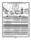
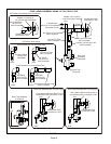
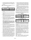
FIGURE 33
*5’ max.
CONDENSATE TRAP LOCATION
(shown with right side exit of condensation)
to drain
Field−Provided Vent
min. 1" Above
Condensate Drain
1" min.
Trap Can Be Installed a
Maximum Of 5’ From Furnace
(PVC Only)
*Piping from furnace must slope down a minimum of
1/4" per ft. toward trap.