


Page 38
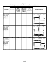
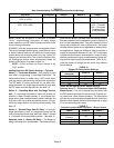
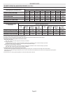
Switches 8 and 9 −− Cooling Mode Blower Speed −− The
unit is shipped from the factory with the DIP switches posi-
tioned for high speed (4) indoor blower motor operation
during the cooling mode. The table below provides the
cooling mode blower speeds that will result from different
switch settings. Refer to tables beginning on page 37 for
corresponding cfm values.
TABLE 18
Cooling Mode Blower Speeds
Speed Switch 8 Switch 9
1 − Low On On
2 − Medium Low Off On
3 − Medium High On Off
4 − High (Factory) Off Off
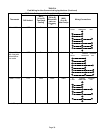
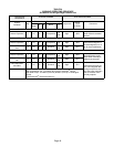
Switches 10 and 11 −− Cooling Mode Blower Speed Ad-
justment −− The unit is shipped from the factory with the
DIP switches positioned for NORMAL (no) adjustment.
The DIP switches may be positioned to adjust the blower
speed by +10% or −10% to better suit the application. Table
19 provides blower speed adjustments that will result from
different switch settings. Refer to tables beginning on page
37 for corresponding cfm values.
With switches 10 and 11 set to ON, motor will bypass ramp-
ing profiles and all delays and will immediately run at se-
lected COOLING speed upon a call for cool. LED will con-
tinue to operate as normal. This mode is used to check
motor operation.
TABLE 19
Cooling Mode Blower Speed Adjustment
Adjustment Switch 10 Switch 11
+10% (approx.) On Off
NORMAL (Factory) Off Off
−10% (approx.) Off On
MOTOR TEST On On
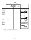
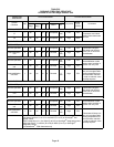
Switches 12 and 13 −− Cooling Mode Blower Speed
Ramping −− Blower speed ramping may be used to en-
hance dehumidification performance. The switches are
factory set at option A which has the greatest effect on
blower motor performance. Table 20 provides the cooling
mode blower speed ramping options that will result from
different switch settings. The cooling mode blower speed
ramping options are detailed below.
NOTE − The off portion of the selected ramp profile only ap-
plies during heat pump operation in dual fuel applications.
TABLE 20
Cooling Mode Blower Speed Ramping
Ramping Option Switch 12 Switch 13
A (Factory) Off Off
B On Off
C Off On
D On On
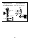
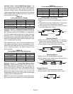
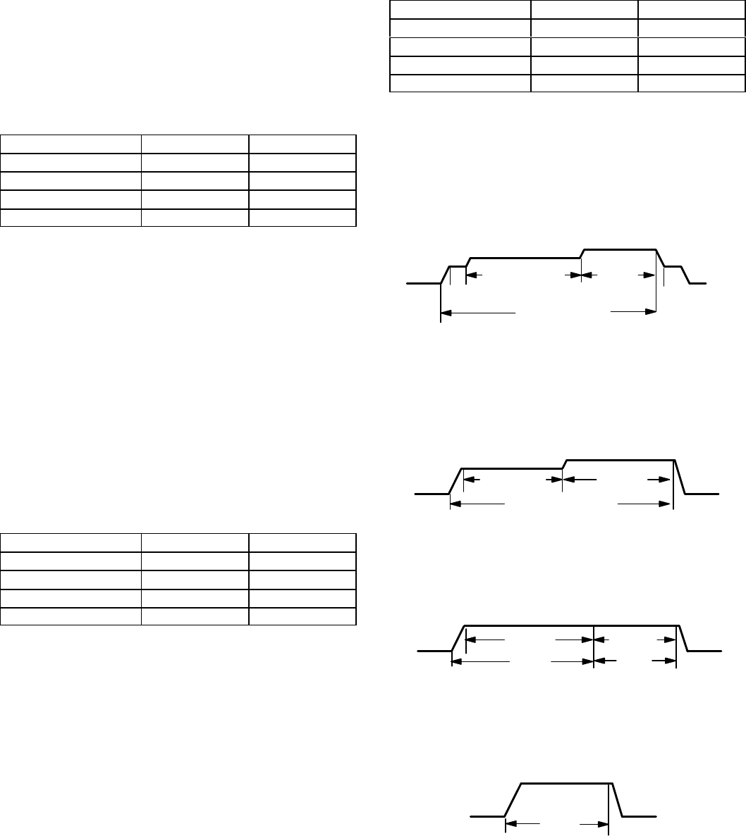
Ramping Option A (Factory Selection)
D Motor runs at 50% for 30 seconds.
D Motor then runs at 82% for approximately 7−1/2 minu-
tes.
D If demand has not been satisfied after 7−1/2 minutes,
motor runs at 100% until demand is satisfied.
D Once demand is met, motor runs at 50% for 30 sec-
onds then ramps down to stop.
OFF
OFF
1/2 MIN
50% CFM
COOLING DEMAND
7 1/2 MIN
82% CFM
100%
CFM
1/2 MIN
50% CFM
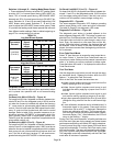
Ramping Option B
D Motor runs at 82% for approximately 7−1/2 minutes. If
demand has not been satisfied after 7−1/2 minutes,
motor runs at 100% until demand is satisfied.
D Once demand is met, motor ramps down to stop.
OFF
OFF
82%CFM
100% CFM
COOLING DEMAND
7 1/2 MIN
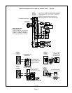
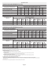
Ramping Option C
D Motor runs at 100% until demand is satisfied.
D Once demand is met, motor runs at 100% for 45 sec-
onds then ramps down to stop.
OFF
OFF
100% CFM
100% CFM
COOLING DEMAND
45 SEC.
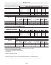
Ramping Option D
D Motor runs at 100% until demand is satisfied.
D Once demand is met, motor ramps down to stop.
OFFOFF
100% CFM
COOLING
DEMAND