


Page 11
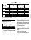
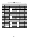
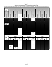
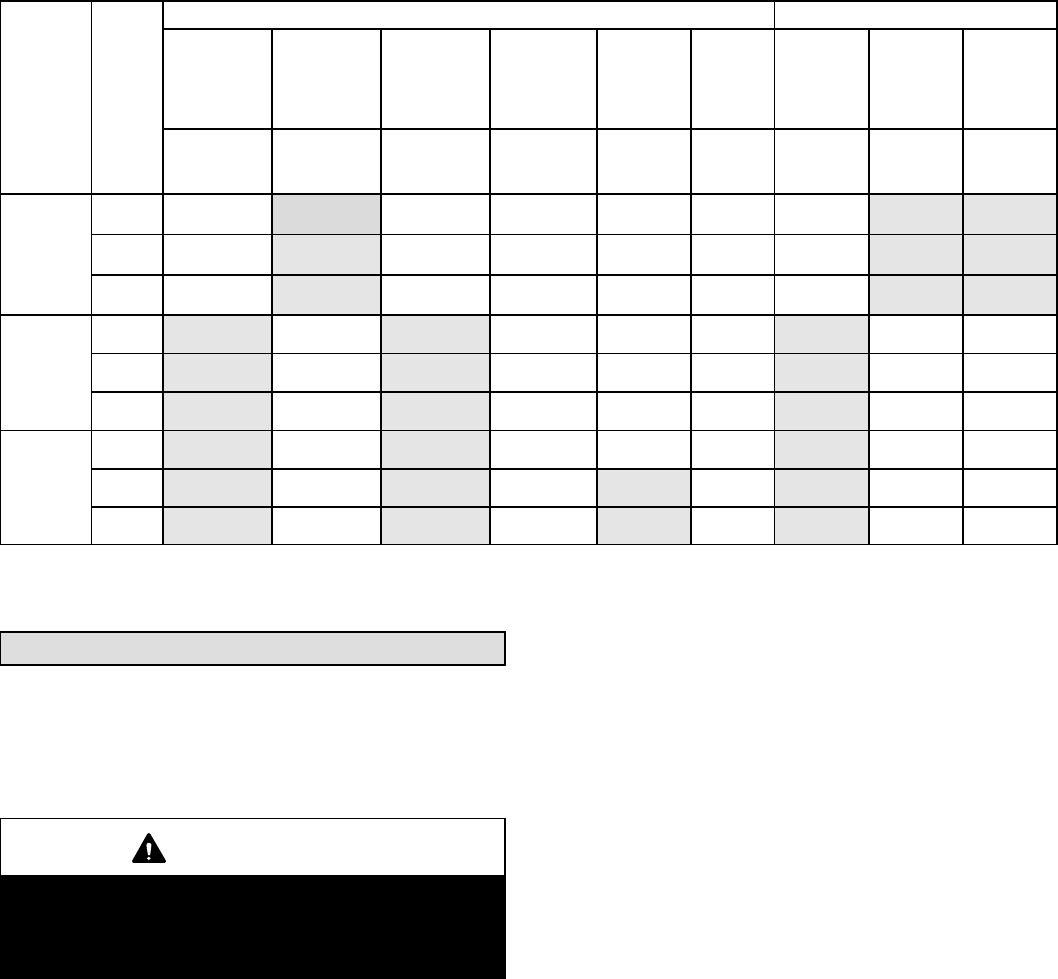
TABLE 5
OUTDOOR TERMINATION KITS USAGE
SLP98DF
UNIT
VENT
PIPE
DIA.
(in.)
STANDARD CONCENTRIC
Outdoor
Exhaust
Accelerator
(Dia. X
Length)
Outdoor
Exhaust
Accelerator
(Dia. X
Length)
2" Wall Plate
Kit
3" Wall Plate
Kit
2" Wall
Ring Kit
Flush-
Mount
Kit
1−1/2"
Concentric
Kit
2"
Concentric
Kit
3"
Concentric
Kit
1−1/2" X 12" 2" X 12"
22G44
or 30G28
44J40
or 81J20
15F74 51W11**
71M80
or
44W92
69M29
or
44W92
60L46
or 44W93
070
2 YES YES YES* YES YES YES
2−1/2 YES YES YES* YES YES YES
3 YES YES YES* YES YES YES
090
2 YES YES YES YES YES YES
2−1/2 YES YES YES YES YES YES
3 YES YES YES YES YES YES
110
2 YES YES YES YES YES YES
2−1/2 YES YES YES YES YES
3 YES YES YES YES YES
*Requires field−provided and installed 1−1/2" exhaust accelerator.
** Kit 51W11 includes h a 1−1/2" accelerator which must be used for all SLP98DFV−070 and −090 installations.
Termination kits 44W92, 44W93, 30G28 and 81J20 approved for use in Canadian installations.
The 44W92 concentric kit includes a 1−1/2" accelerator which must be installed on the exhaust outlet when this kit is used with the SL98DF070V36B furnaces.
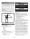
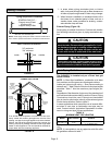
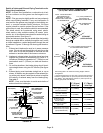
Joint Cementing Procedure
All cementing of joints should be done according to the
specifications outlined in ASTM D 2855.
NOTE − A sheet metal screw may be used to secure
the intake pipe to the connector, if desired. Use a drill
or self tapping screw to make a pilot hole.
DANGER
DANGER OF EXPLOSION!
Fumes from PVC glue may ignite during system
check. Allow fumes to dissipate for at least 5 minutes
before placing unit into operation.
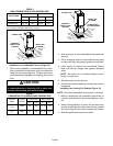
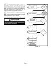
1 − Measure and cut vent pipe to desired length.
2 − Debur and chamfer end of pipe, removing any ridges
or rough edges. If end is not chamfered, edge of pipe
may remove cement from fitting socket and result in a
leaking joint.
3 − Clean and dry surfaces to be joined.
NOTE − Check the inside of vent pipe thoroughly for
any obstruction that may alter furnace operation.
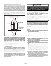
4 − Test fit joint and mark depth of fitting on outside of pipe.
5 − Uniformly apply a liberal coat of PVC primer for PVC or
use a clean dry cloth for ABS to clean inside socket
surface of fitting and male end of pipe to depth of fitting
socket.
6 − Promptly apply solvent cement to end of pipe and in-
side socket surface of fitting. Cement should be ap-
plied lightly but uniformly to inside of socket. Take
care to keep excess cement out of socket. Apply sec-
ond coat to end of pipe.
NOTE − Time is critical at this stage. Do not allow prim-
er to dry before applying cement.
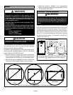
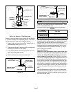
7 − Immediately after applying last coat of cement to pipe,
and while both inside socket surface and end of pipe
are wet with cement, forcefully insert end of pipe into
socket until it bottoms out. Turn PVC pipe 1/4 turn dur-
ing assembly (but not after pipe is fully inserted) to dis-
tribute cement evenly. DO NOT turn ABS or cellular
core pipe.
NOTE − Assembly should be completed within 20 sec-
onds after last application of cement. Hammer blows
should not be used when inserting pipe.
8 − After assembly, wipe excess cement from pipe at end
of fitting socket. A properly made joint will show a
bead around its entire perimeter. Any gaps may indi-
cate a defective assembly due to insufficient solvent.
9 − Handle joints carefully until completely set.