


Page 37
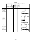
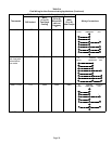
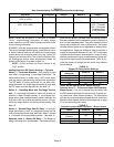
TABLE 15
Non−Communicating Thermostat Selection Switch Settings
Operation Thermostat Switch 1 Switch 2 Switch 3
Variable Capacity Heat
(35% to 100%)
Two−Stage Off On Off
Three−Stage Heat
(35%, 70%, 100%)
Single−Stage On Off 2nd stage delay
OFF = 7 minutes
ON = 12 minutes
3rd stage delay
10 minutes fixed
Two−Stage Heat (W1 70%, W2 100%) Two−Stage Off Off Off
NOTE − When the SLP98DFV is used with an icomfort
Toucht communicating thermostat, all indoor blower
speed selections and DIP switch settings are made by the
communicating thermostat.
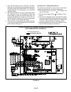
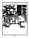
SLP98DFV units are equipped with an integrated control.
This control manages ignition timing, combustion air induc-
er speed, heating mode fan off delays and indoor blower
speeds based on selections made using the control DIP
switches and on−board links. The control includes an inter-
nal Watchguard feature which automatically resets the
ignition control when it has been locked out.
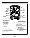
NOTE − All DIP switches are factory shipped in the
OFF" position.
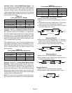
Heating Operation DIP Switch Settings −− Figure 44
Switch 1 −− Thermostat Selection −− This unit may be used
with either a single−stage or two−stage thermostat. The
thermostat selection is made using a DIP switch which
must be properly positioned for the particular application.
The DIP switch is factory−positioned for use with a two−
stage thermostat. If a single−stage thermostat is to be used,
the DIP switch must be repositioned. See table 15.
Switch 2 −− Operating Mode with Two−Stage Thermo-
stat −− If a two−stage thermostat is used, the furnace can
operate in either variable−capacity or conventional two−
stage mode. When variable−capacity mode is selected, the
firing rate of the unit is varied to maximize comfort. Conven-
tional two−stage mode is the factory default setting. See
table 15.
Switch 3 −− Second−Stage Heat On Delay −− If a single−
stage thermostat is used, the integrated control can be
used to energize second−stage heat after either 7 minutes
or 12 minutes of first−stage heat operation. See table 15.
Switches 4 and 5 −− Blower−Off Delay −− The blower−on
delay of 45 seconds is not adjustable. The blower−off delay
(time that the blower operates after the heating demand
has been satisfied) can be adjusted by moving switches 4
and 5 on the integrated control. The unit is shipped from the
factory with a blower−off delay of 90 seconds. The blower
off delay affects comfort and is adjustable to satisfy individ-
ual applications. Adjust the blower off delay to achieve a
supply air temperature between 90° and 110°F at the exact
moment that the blower is de−energized. Longer off delay
settings provide lower supply air temperatures; shorter set-
tings provide higher supply air temperatures. Table 16 pro-
vides the blower off timings that will result from different
switch settings.
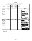
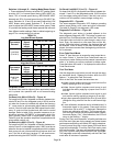
TABLE 16
Blower Off Delay Switch Settings
Blower Off Delay
(Seconds)
Switch 4 Switch 5
60 Off On
90 (factory) Off Off
120 On Off
180 On On
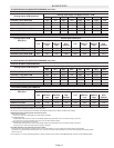
Indoor Blower Operation DIP Switch Settings
Switches 6 and 7 −− Continuous Indoor Fan Operation-
Blower Speed −− The unit is shipped from the factory with
the DIP switches positioned for medium low (2) speed dur-
ing continuous indoor blower operation. The table below
provides the continuous blower speeds that will result from
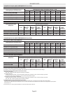
different switch settings. Refer to tables beginning on page
37 for corresponding cfm values.
TABLE 17
Continuous Indoor Blower Operation −− Blower Speeds
Speed Switch 6 Switch 7
1 − Low Off On
2 − Medium Low
(Factory)
Off Off
3 − Medium High On Off
4 − High On On