


Page 19
C
A
E
D
B
A
B
D
D
B
C
A
C
12"
1
1
2
2
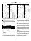
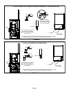
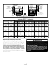
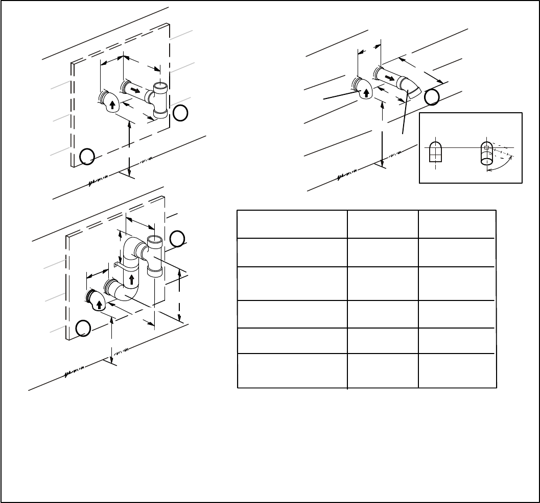
2" (51mm)
Vent Pipe
3" (76mm)
Vent Pipe
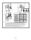
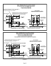
A− Clearance above
grade or average snow
accumulation
B−Horizontal
separation between
intake and exhaust
C−Minimum from
end of exhaust to
inlet of intake
D−Exhaust pipe length
E−Wall support distance
from top of each pipe
(intake/exhaust)
12" (508MM) Min.
12" (508MM) Min.
6" (152MM) Min.
24" (610 MM) Max
9" (227MM) Min.
12" (305MM) Min.
16" (405 MM) Max.
6" (152MM) Max.
6" (152MM) Min.
24" (610 MM) Max
9" (227MM) Min.
12" (305MM) Min.
20" (508MM) Max.
6" (152MM) Max.
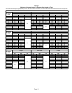
TABLE 8
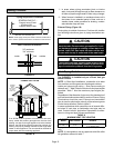
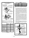
FIGURE 21
1
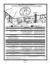
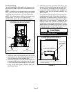
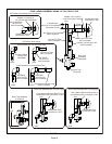
The exhaust termination tee should be connected to the 2" or 3" PVC flue pipe as shown in the illustration. Do
not use an accelerator in applications that include an exhaust termination tee. The accelerator is not required.
2
As required. Flue gas may be acidic and may adversely affect some building materials. If a side wall vent
termination is used and flue gases will impinge on the building materials, a corrosion−resistant shield (24 inches
square) should be used to protect the wall surface. If optional tee is used, the protective shield is recommende-
d. The shield should be constructed using wood, sheet metal or other suitable material. All seams, joints,
cracks, etc. in affected area, should be sealed using an appropriate sealant.
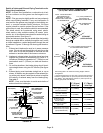
3
Exhaust pipe 45° elbow can be rotated to the side away from the combustion air inlet to direct exhaust away
from adjacent property. The exhaust must never be directed toward the combustion air inlet.
NOTE − See unit installation instructions for proper exhaust pipe termination size reduction.
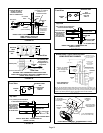
Front View of
Intake and Exhaust
Intake
Exhaust
3
Intake
Exhaust