


Page 50
Service
WARNING
ELECTRICAL SHOCK, FIRE,
OR EXPLOSION HAZARD.
Failure to follow safety warnings exactly could result
in dangerous operation, serious injury, death or
property damage.
Improper servicing could result in dangerous opera-
tion, serious injury, death, or property damage.
Before servicing, disconnect all electrical power to
furnace.
When servicing controls, label all wires prior to dis-
connecting. Take care to reconnect wires correctly.
Verify proper operation after servicing.
At the beginning of each heating season, system should be
checked as follows by a qualified service technician:
Blower
Check the blower wheel for debris and clean if necessary.
The blower motors are prelubricated for extended bearing
life. No further lubrication is needed.
WARNING
The blower access panel must be securely in place
when the blower and burners are operating. Gas
fumes, which could contain carbon monoxide, can
be drawn into living space resulting in personal inju-
ry or death.
Filters
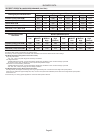
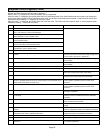
All SLP98DFV filters are installed external to the unit. Fil-
ters should be inspected monthly. Clean or replace the fil-
ters when necessary to ensure proper furnace operation.
Table 3 lists recommended filter sizes.
Exhaust and air intake pipes
Check the exhaust and air intake pipes and all connections
for tightness and to make sure there is no blockage.
NOTE − After any heavy snow, ice or frozen fog event the
furnace vent pipes may become restricted. Always check
the vent system and remove any snow or ice that may be
obstructing the plastic intake or exhaust pipes.
Electrical
1 − Check all wiring for loose connections.
2 − Check for the correct voltage at the furnace (furnace
operating).
3 − Check amp−draw on the blower motor.
Motor Nameplate__________Actual__________
Winterizing and Condensate Trap Care
1 − Turn off power to the unit.
2 − Have a shallow pan ready to empty condensate water.
3 − Remove the drain plug from the condensate trap and
empty water. Inspect the trap then reinstall the drain
plug and refill trap with water.
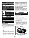
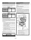
Cleaning Heat Exchanger
If cleaning the heat exchanger becomes necessary, follow
the below procedures and refer to figure 1 when disassem-
bling unit. Use papers or protective covering in front of fur-
nace while removing heat exchanger assembly.
1 − Turn off electrical and gas supplies to the furnace.
2 − Remove the furnace access panels.
3 − Disconnect the 2−pin plug from the gas valve.
4 − Remove gas supply line connected to gas valve. Re-
move the burner box cover and remove gas valve/
manifold assembly.
5 − Remove sensor wire from sensor. Disconnect 2-pin
plug from the ignitor.
6 − Disconnect wires from flame roll−out switches.
7 − Loosen clamps at vent elbow. Disconnect condensate
drain tubing from flue collar. and remove the vent el-
bow.
8 − Remove four burner box screws at the vestibule panel
and remove burner box. Set burner box assembly
aside.
NOTE − If necessary, clean burners at this time. Follow
procedures outlined in Burner Cleaning section.
9 − Mark and disconnect all combustion air pressure tub-
ing from cold end header collector box.
10 − Mark and remove wires from pressure switches. Re-
move pressure switches. Keep tubing attached to
pressure switches
11 − Disconnect the 4-pin plug from the combustion air in-
ducer. Remove two screws which secure combustion
air inducer to collector box. Remove combustion air in-
ducer assembly. Remove ground wire from vest pan-
el.
12 − Remove electrical junction box from the side of the fur-
nace.
13 − Remove cold end header box.
14 − Mark and disconnect any remaining wiring to heating
compartment components. Disengage strain relief
bushing and pull wiring and bushing through the hole in
the blower deck.
15 − Remove the primary limit from the vestibule panel.
16 − Remove two screws from the front cabinet flange at
the blower deck. Spread cabinet sides slightly to allow
clearance for removal of heat exchanger.
17 − Remove screws along vestibule sides which secure
vestibule panel and heat exchanger assembly to cabi-
net. Remove two screws from blower rail which secure
bottom heat exchanger flange. Remove heat ex-
changer from furnace cabinet.
18 − Back wash heat exchanger with soapy water solution
or steam. If steam is used it must be below 275°F
(135°C) .