


Operating Instructions
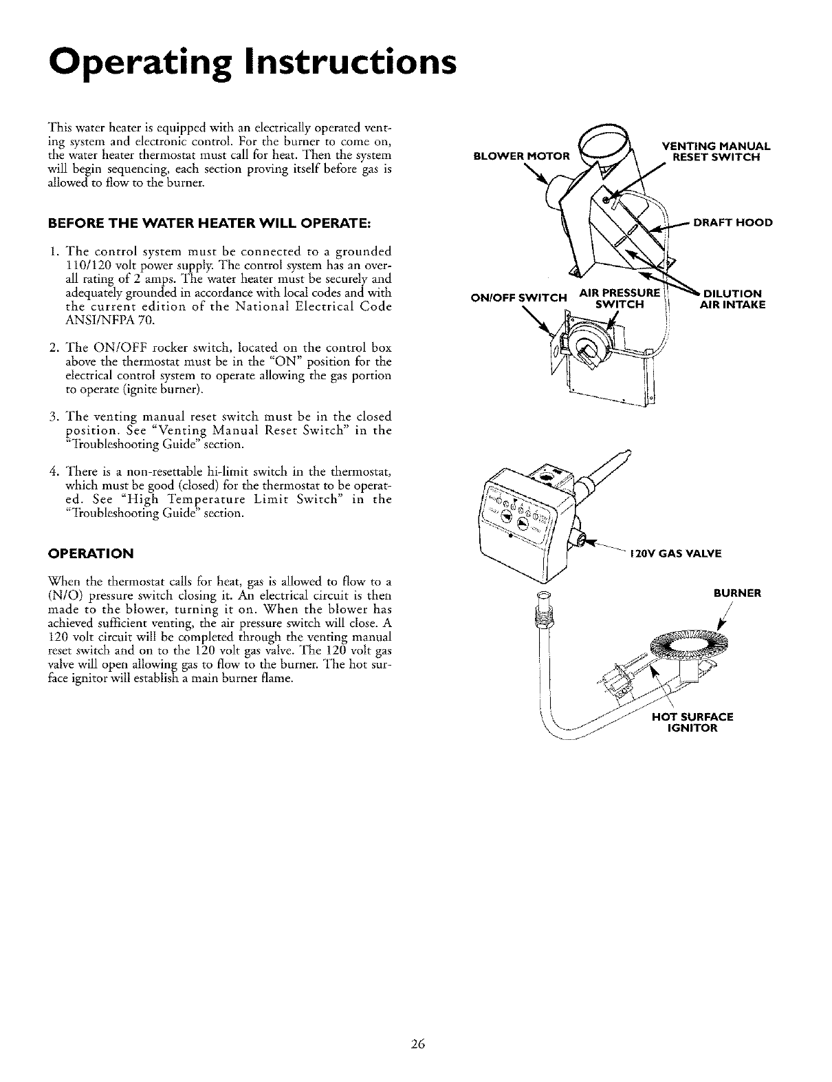
This water heater is equipped with an electrically operated vent-
ing system and electronic control. For the burner to come on,
the water heater thermostat must call for heat. Then the system
will begin sequencing, each section proving itself before gas is
allowed to flow to the burner.
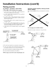
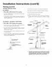
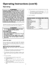
BLOWER MOTOR
VENTING MANUAL
RESET SWITCH
BEFORE THE WATER HEATER WILL OPERATE:
1. The control system must be connected to a grounded
110/120 volt power supply. The control system has an over-
all rating of 2 amps. The water heater must be securely and
adequately grounded in accordance with local codes and with
the current edition of the National Electrical Code
ANS1/NFPA 70.
2. The ON/OFF rocker switch, located on the control box
above the thermostat must be in the "ON" position for the
electrical control system to operate allowing the gas portion
to operate (ignite burner).
3. The venting manual reset switch must be in the closed
position. See "Venting Manual Reset Switch" in the
"'ii-oubleshooting Guide" section.
4. There is a non-resettable hi-limit switch in the thermostat,
which must be good (closed) for the thermostat to be operat-
ed. See "High Temperature Limit Switch" in the
"_I_oubleshooting Guide" section.
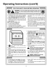
OPERATION
When the thermostat calls for heat, gas is allowed to flow to a
(N/O) pressure switch closing it. An electrical circuit is then
made to the blower, turning it on. When the blower has
achieved sufficient venting, the air pressure switch will close. A
120 volt circuit will be completed through the venting manual
reset switch and on to the 120 volt gas valve. The 120 volt gas
valve will open allowing gas to flow to the burner. The hot sur-
face ignitor will establish a main burner flame.
DRAFT HOOD
ON/OFF SWITCH AIR PRESSURE
\ CH
_ '
AIR INTAKE
120V GAS VALVE
BURNER
_' /7 HOTSURFACE
26