


Installation Instructions (cont'd)
Facts to Consider About the
Location (cont'd)
AWARNING
This water heatermust not be installeddirectlyoncarpeting.
Carpeting must be protected by a metal or wood panel
beneaththe applianceextendingbeyondthe full width and
depth of the applianceby at least3 inches(76.2mm) in an)
direction,or ifthe applianceisinstalledinanalcoveor closet
the entire floormust be coveredby thepanel.Failureto hee¢
thiswarningmay result ina fire hazard.
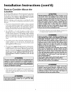
&WARNING
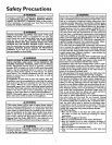
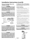
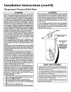
Minimum clearances between the water heater and com-
bustible construction are 0" at the sides and rear, 5" at the
front, and 0" from the vent pipe. Clearance from the top of
the jacket is 12".Provide 24 inches front clearance for servic-
ing and adequate clearance between the jacket top & ceiling
for servicing the flue area. (See Figure I). Refer to the label
on the water heater adjacent to the gas control valve for all
clearances.
12" MAX
V N[(A[((}N
AIR
)_ NIN 3_
Figure I ]
TOPVIEW -[_" MIN.
OF CL{}SET .')_ ViEW
WTI OUT DOOR OF (lOSE[
_2" MAX. WI]H D{){>}i
AIR [>LCI
Combustion Air and Ventilation
When determining the installation location for a power vent
water heater, snow accumulation and drifting should be consid-
ered in areas where applicable.
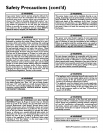
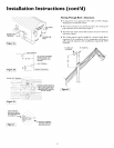
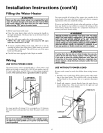
VENTING CLEARANCES
• 0" clearance for 3" (and optional 2") PVC, ABS or CPVC
Schedule 40 vent piping from combustible surfaces.
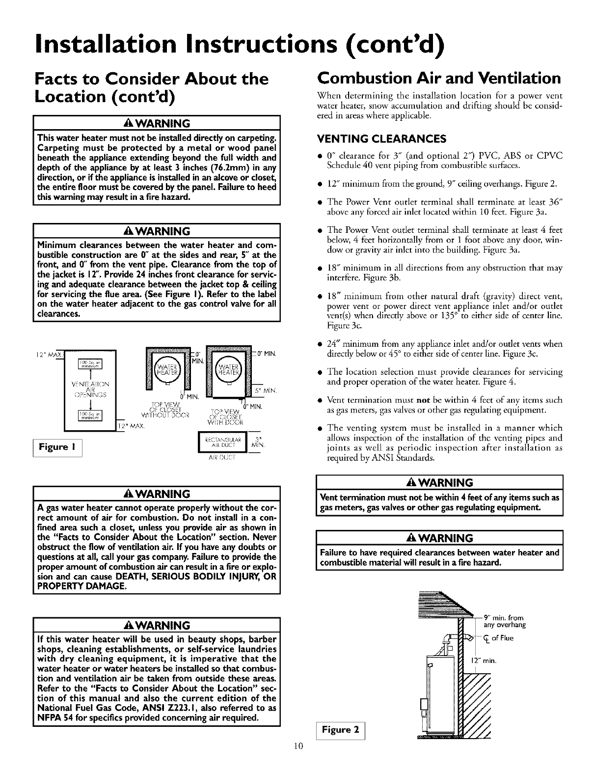
• 12"minimum from the ground, 9" ceiling overhangs. Figure 2.
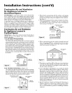
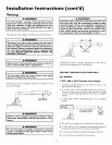
• The Power Vent outlet terminal shall terminate at least 36"
above any forced air inlet located within 10 feet. Figure 3a.
• The Power Vent outlet terminal shall terminate at least 4 feet
below, 4 feet horizontally from or 1 foot above any door, win-
dow or gravity air inlet into the building. Figure 3a.
• 18" minimum in all directions from any obstruction that may
interf?re. Figure 3b.
• 18" minimum from other natural draft (gravity) direct vent,
power vent or power direct vent appliance inlet and/or outlet
vent(s) when directly above or 135° to either side of center line.
Figure 3c
a 24" minimum from any appliance inlet and/or outlet vents when
directly belowor 45° to either side of center line. Figure 3c.
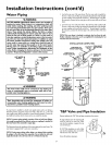
• The location selection must provide clearances for servicing
and proper operation of the water heater. Figure 4.
• Vent termination must not be within 4 feet of any items such
as gas meters, gas valvesor other gas regulating equipment.
• The venting system must be installed in a manner which
allows inspection of the installation of the venting pipes and
joints as well as periodic inspection after installation as
required by ANSI Standards.
_, WARNING
A gaswater heater cannot operate properly without the cor-
rect amount of air for combustion. Do not install in a con-
fined area such a closet, unless you provide air as shown in
the "Facts to Consider About the Location" section. Never
obstruct the flow of ventilation air. If you have any doubts or
questions at all, call your gascompany. Failure to provide the
proper amount of combustion air can result in a fire or explo-
sion and can cause DEATH, SERIOUS BODILY INJURY, OR
PROPERTY DAMAGE.
_,WARNING
If this water heater will be used in beauty shops, barber
shops, cleaning establishments, or self-service laundries
with dry cleaning equipment, it is imperative that the
water heater or water heaters be installed so that combus-
tion and ventilation air be taken from outside these areas.
Refer to the "Facts to Consider About the Location" sec-
tion of this manual and also the current edition of the
National Fuel Gas Code, ANSI Z223.1, also referred to as
NFPA 54 for specifics provided concerning air required.
10
&WARNING J
Vent termination must not be within 4 feet of any items such as
gas meters, gas valves or other gas regulating equipment.
& WARNING heaterand
Failureto haverequired clearancesbetweenwater
combustiblematerialwill result in afire hazard.
Figure 2 1