


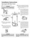
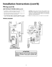
Installation Instructions (cont'd)
Combustion Air and Ventilation
for Appliances Located in
Unconfined Spaces
Unconfined Space is a spacewhose volume is not less than 50 cubic
feet per 1,000Btu per hour of the aggregateinput rating of all appli-
ances installedin that space. Rooms communicating directlywitll the
space in which tile appliancesare installed, through openingsnot fur-
nished with doors, are considereda part ofthe unconfined space.
In unconfined spaces in buildings, infiltration may be adequate to
provide air for combustion, ventilation and dilution of flue gases.
However, in buildings of tight construction (for example, weather
stripping, heavilyinsulated, caulked,vaporbarrier, etc.), additional air
may need to beprovided usingthe methods described in Combustion
Air and Ventilation forAppliancesLocated in Confined Spaces.
Combustion Air and Ventilation
for Appliances Located in
Confined Spaces
Confined Space is a space whose volume is less than 50 cubic feet per
1,000 Btu per hour of the aggregate input rating of all appliances
installed in that space.
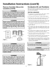
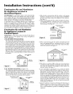
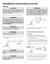
a. ALL AIR FROM INSIDE BUILDINGS:
(See Page 10 Figure 1, and Figure 6 below)
"Ille confined space shall be provided with two permanent openings
communicating directly with an additional room(s) of sufficient
volume so that the combined volume of all spaces meets the criteria
lbr an unconfined space. "Ille total input of all gas utilization equip-
ment installed in the combined space shall be considered in making
this determination. Each opening shall have a mininmm flee area of
one square inch per 1,000 BTU per hour of the total input rating of
all gas utilization equipment in the confined space, but not less than
100 square inches. One opening shall commence within 12 inches
of the top and one commencing within 12 inches of the bottom of
the endosurc.
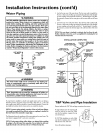
VENT THROUGH
1. When directly communicating with the outdoors, each opening
shall have a minimum free area of 1 square inch per 4,000 BTU
per hour of total input rating of all equipment in the enclosure.
(See Figm'e 7.)
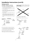
2. When communicating with the outdoors through vertical ducts,
each opening shall have a minimum free area of 1 square inch
per 4,000 BTU per hour of total input rating of all equipment
in the enclosure. (See Figure 8.)
I Figure 8 ]
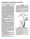
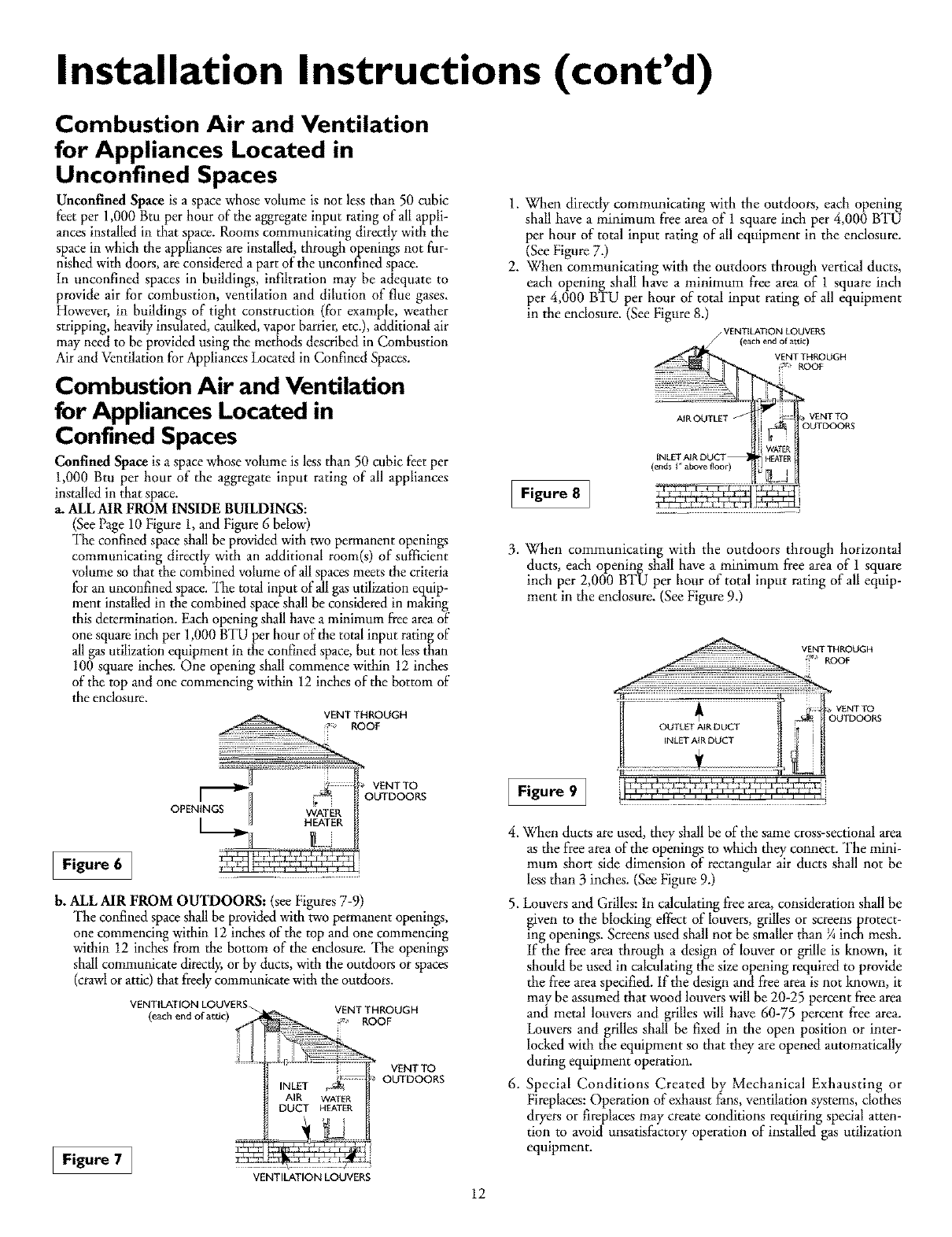
3. When communicating with the outdoors through horizontal
ducts, each openingshall have a minimum free area of 1 square
inch per 2,000 BTU per hour of total input rating of all equip-
ment in the enclosure. (SeeFigure 9.)
Figure 6 ]
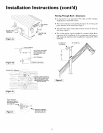
b. ALL AIR FROM OUTDOORS: (see Figures 7-9)
The confined space shall be provided with two permanent openings,
one commencing within 12 inches of the top and one commencing
within 12 inches from tile bottom of the enclosure. The openings
shall communicate directly, or by ducts, with the outdoors or spaces
(crawl or attic) that freely communicate with the outdoors.
VENTILATION LOUVERS_
(each end of attic)
VENT THROUGH
2 ROOF
VENT TO
OUTDOORS
Figure 7 ]
Figure 9]
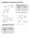
4. When ducts are used, they shall be of the same cross-sectional area
as the flee area of the openings to which they connect. The mini-
mum short side dimension of rectangular air ducts shall not be
less than 3 inches. (See Figure 9.)
5. Louvers and Grilles: In calculating flee area, consideration shall be
given to the blocking effect of louvers, grilles or screens protect-
ing openings. Screens used shall not be smaller than ¼ inch mesh.
If the flee area through a design of louver or grille is known, it
should be used in calculating the size opening required to provide
the free area specified. If the design and flee area is not known, it
may be assumed that wood louvers will be 20-25 percent flee area
and metal louvers and grilles will have 60-75 percent free area.
Louvers and grilles shall be fixed in the open position or inter-
locked with the equipment so that they are opened automatically
during equipment operation.
6. Special Conditions Created by Mechanical Exhausting or
Fireplaces: Operation of exhaust fans, ventilation systems, clothes
dryers or fireplaces may create conditions requiring special atten-
tion to avoid unsatisfactory operation of installed gas utilization
equipment.
VENTILATION LOUVERS
12