


Installation Instructions (cont'd)
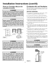
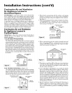
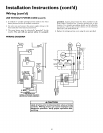
•LESSTHAN
120"
POWER VENTJ
TERMINAL 12"rain.
Figure 3a I
FORCED AIR
INLET
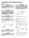
VENT TERMINAL
f
18"TO WALL OR OTHER
J_lS" MIN. _ OBSTRUCTIONS THAT
MAY INTERFEREWFTH
VENTING.
VENT TERMINAL
Figure 3b I
CORNER OF BUILDING
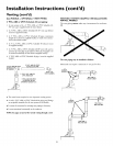
POWER VENTTERMINAL _js -- ".
-- _ , / DIRECT VENT, POWER VENT
_ _/ OR POWER D,RECT VENT
24" _J_!-- APPDANCEINLETAND/OR
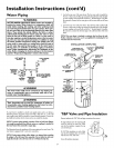
Venting Through Roof- Clearances
• 0' clearancefor Y' (or opt'onal 2") PVC, ABS,or CPVC Schedule
40 piping fromcombustiblesurfaces.
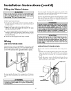
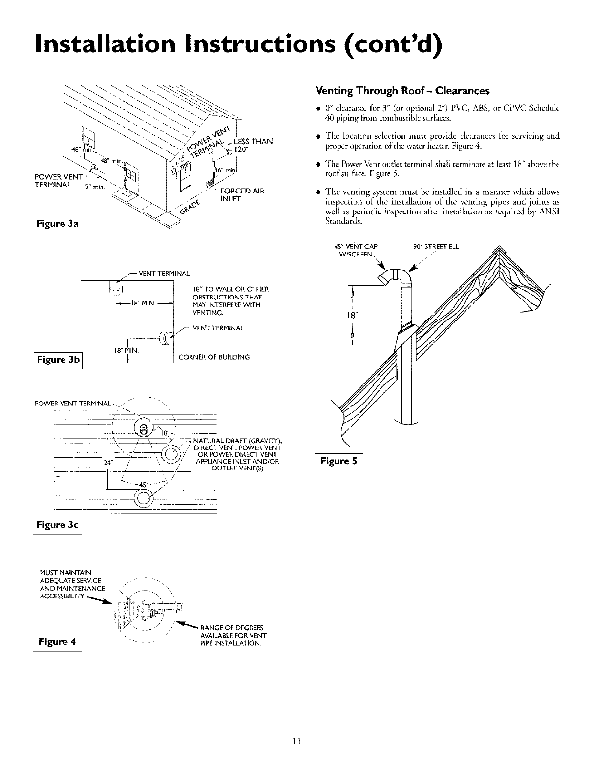
• "The location selection must provide clearances for servicing and
proper operation of the water heater• Figure 4.
• "ThePower Vent outlet terminal shall terminate at least 18" above the
roof surface. Figure 5.
• The venting system must be installed in a manner which allows
inspection of the installation of the venting pipes and joints as
well as periodic inspection aiier installation as required by ANSI
Standards.
45° VENT CAP 90°STREET ELL
N
Figure 5 ]
Figure 3c]
MUST MAINTAIN
ADEQUATE SERVICE
Figure 4 ]
AVAILABLE FOR VENT
.... " PIPEINSTALLATION.
11