


21
1
(25mm)
3/8
(8mm)
Min.
1/8
(3mm)
Min.
Ignitor
Thermopile
Thermocouple
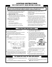
Checking the System
1. Purging the Gas Line: When lighting the appli-
ance for the first time it will take a few mo-
ments to clear the gas line of air. Once this
purge is complete, the appliance will operate as
described in the lighting instructions located on
the stove’s rating plate. All subsequent lightings
of the stove will not require such purging of the
gas line.
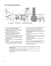
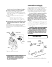
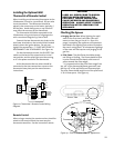
2. Pilot Flame: The pilot flame should be steady,
not lifting or floating. The flame should be blue
in color around the pilot hood, with traces of
yellow toward the outer edges.
It is imperative that the pilot flame engulf the
top 3/8” of the thermopile(power generator) and
the top 1/8” of the quick drop out thermocouple.
The pilot flame should project out of the pilot hood
1” at all three ports. See Figure 25.
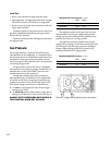
Installing the Optional Wall
Thermostat of Remote Control
When installing a wall mounted thermostat to the
Lillehammer, it must be 750 millivolt DC two-wire
circut thermostat. The thermostat should be
placed in the same room as the heater, typically 5’
off the floor. Avoid drafty areas or any area that
may affect the accuracy of the thermostat.
The thermostat should be connected to the
Lillehammer using a minimum of 16 gauge wire
with a maximum length of 35 feet of wire.
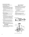
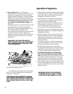
Connect the two thermostat wire leads to the
two lower terminals on the terminal block located
directly above the ignitor button. Do not over-
tighten the connections. IT IS NOT NECESSARY TO
DISCONNNECT ANY OTHER WIRES. See Figure 24.
For the thermostat to work, the On/Off/T-Stat
switch on the back of the stove must be in the T-
stat position, and the pilot light must be running,
as it is the power source for the thermostat.
At the thermostat the two wires should be
connected to the two connections screws on the
thermostat base plate per the manufacturers
instructions.
Remote Control
When using a remote, the remote receiver should be
wired to the terminal block the same way the
thermostat would be. See the instructions above.
CAUTION:
LABEL ALL WIRES PRIOR TO DISCON-
NECTION WHEN SERVICING THE
CONTROLS. WIRING ERRORS CAN
CAUSE IMPROPER AND DANGEROUS
OPERATION. ALWAYS VERIFY PROPER
OPERATION AFTER SERVICING THE
APPLIANCE.
Figure 25. Pilot Location and Correct Appearance
Figure 24. Thermostat / Remote Control Wiring
Diagram.
Burner Tube
TERMINAL
BLOCK
VALVE
THERMOPILE
ROCKER
SWITCH
ON
OFF
STAT
OPTIONAL
THERMOSTAT
or
REMOTE
CONTROL
TH
TP
TH
TP
Pilot
Assembly