


16
Gas Conversion Procedure
See Figure 29, page 25 for parts identification.
1. Turn off gas supply to the stove.
2. Remove the stove Top Plate (3).
3. Remove the Front Panel. Using a 10mm open-
end wrench, loosen the two bolts holding the
Front Panel (1) to the side panels (2). (Note: You
do not have to remove these bolts.) Pull the
Front Panel away from the stove and lift off of
Bottom Plate.
4. Release the Glass Retainer Clips (12) on top of
the firebox and carefully lift the Glass Panel up and
out.
5. Remove the Logs (14) using care to avoid chip-
ping or other damage.
6. Lift out the Air Deflector (17). Remove the Air
Divider (16) by lifting right side and slowly
rotating forward.
7..Remove Burner Tube (15): Using a ¼” nut driver,
remove the two screws securing the Burner Tube
to the stove bottom. Lift out the Burner Tube.
WHEN RE-INSTALLING THE BURNER TUBE, BE
SURE THAT THE TUBE IS PULLED FORWARD IN
THE MOUNTING HOLES. Secure with the two 1/
4” screws.
8. Remove the Burner Orifice Holder Shield (18)
around the orifice. Using a 1/4” nut driver
remove the screw attaching the shield to the rear
wall of the firebox. Slide the shield left and
remove.
9. Change the Main Burner Orifice (38). Use a ½”
open end wrench to remove the burner orifice and
replace with the appropriate orifice supplied in the kit.
#48 for Natural Gas
3/64” for Propane
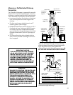
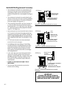
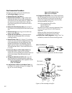
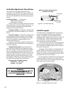
10. Adjust the Air Shutter on the Burner Tube (15)
to allow for the proper mixing of air and gas. See
fig. 16. The correct settings:
Open 1/8” for Natural Gas
Open 3/4” for Propane
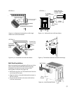
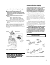
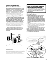
11. Change the Pilot Orifice. From within the firebox,
pull the Spring Clip back to release the Pilot Hood
from the Pilot Base. Use the 4m mm hex key to
remove the original Pilot Orifice from the base,
(counterclockwise). See fig. 17.
Install the appropriate pilot orifice:
#51 for Natural Gas
#30 for Propane.
Be certain the orifice is securely tightened. If the
orifice is loose, gas flow will not be properly
regulated.
Replace the Pilot Hood onto the base by re-
engaging the spring clip around its collar.
12. Replace the variable Regulator. Using a Torx T-20
screwdriver, remove the three mounting screws
Pilot Hood
Pilot Orifice
Pilot Base
Spring
Clip
Figure 17. Pilot assembly and orifice.
Figure 16. Air Shutter adjustment and Burner Orifice.
Open 1/8” for Natural Gas
Open 3/4” for Propane
Air Shutter
Burner Orifice
Burner Tube