


18
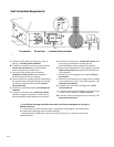
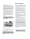
Leak Test:
• Mix a 50-50 solution of water and dish soap.
• Light appliance- see lighting instructions on page
21 of this manual or on the stove’s rating plate.
• Brush or spray all joints and connections with the
soapy water solution.
If bubbles appear at any connection or seam or a
gas odor is detected immediately turn gas control
knob to the OFF position.
Tighten or reconnect the leaking joint and retest
for any gas leaks.
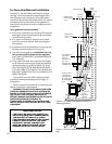
Gas Pressure
Correct gas pressure is essential for efficient and
safe operation of this appliance. It is important that
the correct pressure is established at the time of the
installation. Proper gas pressure provides a consis-
tent flow of gas to the appliance and is instrumental
in checking for gas leaks.
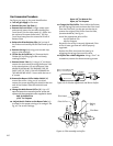
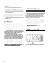
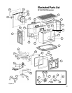
The gas control valve on the stove is equipped
with pressure test points for gauge connections. It is
possible then to test SUPPLY/INLET pressure and
manifold pressure at the appliance.
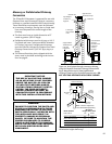
Testing the available gas pressure should be
done by attaching a manometer to the appropriate
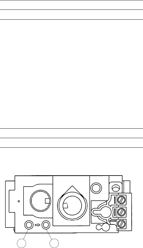
test point on the valve. The gauge connections are
located on the front of the valve under the On/Off/
Pilot- knob. Gauge connections are identified by:
E - for Inlet or supply pressure (the amount of gas
coming to the valve.)
A - for Manifold pressure (the amount of gas that is
coming out of the valve to the burner.) See fig. 20.
ALWAYS TEST PRESSURES WITH REGULA-
TOR CONTROL KNOB SET ON HIGH.
Required Inlet Gas Pressures (in. W.C.)
MIN. MAX.
NATURAL GAS 5.0 7.0
PROPANE 11.0 13.5
The appliance and its main gas valve must be
disconnected from the gas supply piping system
during any pressure testing on that system at test
pressures in excess of 1/2 psig (3.5kPa).
The appliance must be isolated from the gas
supply line by closing its individual manual gas shut-
off valve (gas cock) during any pressure testing of
the gas supply piping system that is equal to or
exceeds pressures of 1/2 psig (3.5kPa).
Required Manifold Pressure
(in. W.C.)
MIN. MAX.
NATURAL GAS 2.2 3.5
PROPANE 5.5 10.0
Figure 20. Supply and Manifold pressure test points.
A
E