


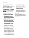
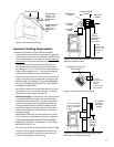
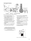

Restrictor Sliders
First Restriction
Setting - install
screw into the
OUTER hole of
sliders.
Second Restriction
Setting - screw
installed into
MIDDLE hole of
slider.
Figure 5. Vent restrictor settings.
Horizontal Venting Requirements
Follow these guidelines if any part of the installation
incorporates a horizontal run or terminates horizontally.
The maximum horizontal run made directly off the rear
of the stove shall be no more than 12" and must then be
connected to a 14" snorkel cap (Simpson Dura-vent #982).
The horizontal termination cap must maintain a 3"
clearance to any overhead combustible projections
exceeding 2 1/2" or less. Maintain 12" clearance from
projections exceeding 2 1/2". See Figure 8, page for
complete termination clearance information.
Any horizontal run of vent must be level or have a 1/4"
rise for every foot of run toward the termination cap.
NEVER ALLOW THE VENTING TO SLOPE DOWNWARD,
AS HIGH TEMPERATURES MAY RESULT AND CREATE A
HAZARDOUS CONDITION.
Vent Pipe Clearance to Combustible Materials: For all
horizontal runs, a 2" top clearance and a 1" side and
bottom clearance must be maintained.
Wall Pass-through: A minimum 10" X 10" square cutout
is required to maintain proper clearances through
combustible wall construction. The opening must be
framed in. Simpson Dura-Vent Wall Thimble #942 or
Secure Vent Wall Radiation Shield SV4RSM must be
used for the wall pass-through. Optional decorative
plates are available to finish the interior side of the
wall pass-through.
IMPORTANT: Follow the vent manufacturers installa-
tion instructions provided with each vent component.
DO NOT FILL AIR SPACE WITH ANY TYPE OF INSULATION.
MAINTAIN THE PROPER CLEARANCES TO THE TERMI-
NATION CAP. SEE FIG. 10.
Do not recess the termination cap into a wall or siding.
Install a Vinyl Siding Standoff between the vent cap
and the exterior wall (Simpson Dura-Vent #950). to
protect vinyl siding from overheating.
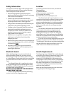
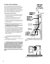
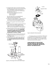
Figure 6. Minimum Vertical Vent - Simpson Dura-
Vent part numbers shown.
7
NOTE:
SHORT LEGS
REDUCE THE
HEIGHT BY
2 1/4.
24 length
#904B
90° Elbow
#990B
55 3/4
Floor to
centerline of
minimum
vertical rise
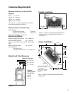
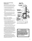
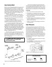
Figure 7. Horizontal terminal to corner.
Simpson Dura-Vent 45°
Elbow #945B
12 Max.
Horizontal run
into a 14
Snorkel
Simpson Dura-
Vent (#906B)
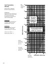
14 Snorkel
Simpson
Dura-Vent
(#982)
12 Max. Horizontal
run into a 14 Snorkel
Simpson Dura-Vent
(#906B)
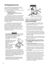
Figure 7a. Horizontal terminal directly off stove
must use a 14 Snorkel termination.
Rear Exit
Centerline
24 3/4
628 mm
Wall Thimble
#942B
Horizontal Length
12 Max.
Wall Plate
#940B