NOTE: Vertical termination may result in reduced
flame height and heat output due to the suction
of natural draft.
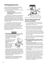
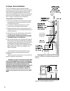
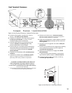
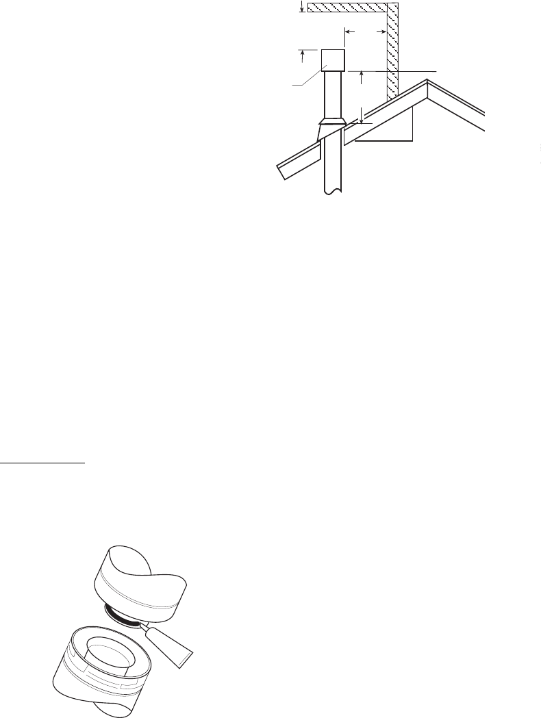
· Vertical Termination Height: In no case shall any
discharge opening on the cap be less than 2' (610
mm) horizontally from the roof surface. See Figure 4.
· A firestop is required at every floor. The opening
should be framed to 10" X 10" inside dimension.
Jøtul recommends the use of Simpson Dura-Vent
Firestop (#963).
· Any venting that is exposed above the first floor,
regardless of attic space or living space, must be
enclosed. Always maintain the required 1" clear-
ance from all sides of the vertical vent system.
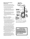
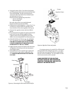
· It may be necessary to add restriction to a vertical
venting installation, so that the draft is not too
strong and creates incomplete combustion.
The Allagash is equipped with sliding restriction
plates that can be adjusted to compensate for
excessive draft. See Figure 5.
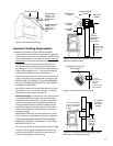
Venting Requirements
There are two types of venting configurations ap-
proved for use with the Allagash gas stove - Horizon-
tal Termination and Vertical Termination.
The GF3 DVII Allagash is approved for use with the
following vent components:
Simpson Dura-Vent GS
Secure Vent - Security Chimneys Intl. Ltd.
Amerivent Direct
Installation of any components not manufactured
or approved by Jøtul or failure to meet all clearance
requirements will void all warranties and could result
in property damage, bodily injury, or serious fire. Use
parts from one manufacturer only - DO NOT MIX VENT
COMPONENTS FROM DIFFERENT MANUFACTURERS IN
THE SAME SYSTEM.
The approved vent configurations described
herein are derived from extensive testing under
controlled laboratory conditions. Gas appliance
performance can be negatively affected by variables
present in the installation environment, i.e: strong
prevailing winds, snow accumulation, etc. These
conditions should be taken into consideration by the
installer and stove owner.
Vertical Venting Requirements
(Vertical Termination)
· The minimum height of a vertically terminated
system shall be no less than 7'. The maximum
height shall be no more than 35'.
· With steep roofs, nearby trees, and predominant
windy conditions, poor draft or down draft condi-
tions can occur. In these cases, increasing the
height of the vent may improve the situation.
· If an offset or elbow is necessary in the vertical
rise, it is important to support the vent pipe every
three feet, to avoid excessive stress on the offsets.
Jøtul recommends the use of Simpson Dura-Vents
Wall Straps. (#988).
· Whenever possible use 45° elbows opposed to 90°
elbows. This offers less restrictions for the flow of
flue gases and intake air.
6
SEALANT
IMPORTANT
JOINT SEALING REQUIREMENT: APPLY A 1/8 BEAD
OF HIGH-TEMPERATURE (750°F) SEALANT TO THE
MALE SECTION OF THE INNER VENT PIPE.
THE CEMENT SHOULD FORM A
SEAL BETWEEN THE INNER AND
OUTER PIPES.
NEVER MODIFY ANY VENTING
COMPONENT, OR USE ANY
DAMAGED VENTING
PRODUCT.
FOLLO THE INSTALLATION
INSTRUCTIONS PRO-
VIDED BY THE VENT
MANUFACTURER FOR
EACH VENT PART.
THE GAS APPLIANCE AND VENT SYSTEM MUST BE
VENTED DIRECTLY TO THE OUTSIDE OF THE BUILD-
ING AND NEVER ATTACHED TO A CHIMNEY SERVING
A SOLID FUEL OR GAS BURNING APPLIANCE. EACH
DIRECT VENT GAS APPLIANCE MUST HAVE ITS OWN
SEPARATE VENT SYSTEM. COMMON VENT SYS-
TEMS ARE PROHIBITED.
IF VENTING SYSTEM IS DISASSEMBLED FOR ANY
REASON, REINSTALL PER THE INSTRUCTIONS PRO-
VIDED FOR THE INITIAL INSTALLATION.
Figure 4. Vertical Vent Roof Penetration Height.
2 ft.
min.
Horizontal Overhang
Vertical Wall
12
Roof Pitch
is X / 12
X
Termination
Cap
2 ft.
min.
Lowest
Discharge
Opening
2 ft.
min.
2 ft. = minimum height from
roof to lowest discharge opening


