Optional Wall Thermostat or
Remote Control
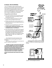
When installing a wall mounted thermostat to the
Allagash it must be 750 millivolt DC two-wire circuit
thermostat. The thermostat should be placed in the
same room as the heater, typically 5 off the floor.
Avoid drafty areas or any area that may effect the
accuracy of the thermostat.
The thermostat should be connected to the
Allagash using a minimum of 16 gauge wire with a
maximum length of 35 feet of wire.
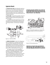
Connect the two thermostat wire leads to the two
lower terminals on the terminal block located directly
above the ignitor button. Do not overtighten the
connections. IT IS NOT NECESSARY TO DISCONNECT
ANY OTHER WIRES. See Figure 23.
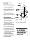
For the thermostat to work the On/Off/T-Stat
switch on the back of the stove must be in the T-stat
position, and the pilot light must be running, for it is
the power source for the thermostat.
At the thermostat the two wires should be
connected to the two connections screws on the
thermostat base plate per the manufacturers
instructions.
Remote Control
The remote receiver should be wired to the terminal
block the same as the thermostat. See the instruc-
tions above.
CAUTION:
LABEL ALL WIRES PRIOR TO
DISCONNECTION WHEN SERVICING
THE CONTROLS. WIRING ERRORS
CAN CAUSE IMPROPER AND
DANGEROUS OPERATION. ALWAYS
VERIFY PROPER OPERATION AFTER
SERVICING THE APPLIANCE.
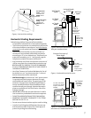
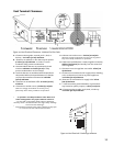
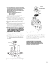
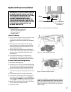
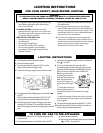
Figure 22. Attaching the blower wire harness.
Snapstat
(attached to
blower bracket)
Wire Harness
Plug
BLOWER
HI/LO
SWITCH
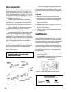
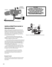
Figure 23. Wiring Diagram / Remote or Thermostat
TERMINAL
BLOCK
VALVE
THERMOPILE
ROCKER
SWITCH
ON
OFF
STAT
OPTIONAL
THERMOSTAT
or
REMOTE
CONTROL
TH
TP
TH
TP
18