


Blower Kit Contents:
Blower with mounting bracket
Snapstat and Wiring Harness
Hi/Low/Off Switch
two 6mm bolts
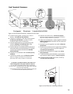
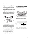
Attach the Blower
1. Locate the two raised bosses on the bottom back
of the stove. See Figure 19. The blower is
mounted to the stove using these two threaded
holes.
2. With the blower bracket and snapstat facing
upward, align the two middle mounting holes on
the bracket with the two threaded holes on the
bottom back of the stove.
3. Use the two 6mm bolts to attach the blower to
the stove. Be sure to tighten the bolts so that the
blower is drawn upward and tight against the
stove bottom.
4. The snapstat (thermodisc), attached to the
blower bracket, should be inserted under the
stove bottom to make contact with the firebox!
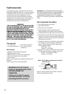
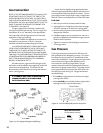
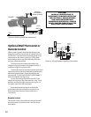
Connect the Blower Wiring Harness
1. Lift off the stove top plate.
2. Loosen (BUT DO NOT REMOVE) the 10 mm bolt holding
the switch box to the side of the stove (left rear
corner of the stove), and lift out the switch box.
3. Remove the blank switch from the box. (Hint:
break the retaining tabs holding the switch in the
box.)
4. Insert the new HI/OFF/LO switch into the box.
5. Connect the insulated wires from the blower to
three leads on the HI/OFF/LO switch. BLACK wire
to the HI position, WHITE wire to the OFF position,
and the RED wire to the LO position. See Fig. 22.
6. Reattach the switch box to the side of the stove.
Be sure all wires are unobstructed.
7. Replace top plate.
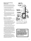
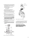
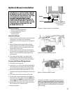
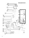
Figure 19. Blower and gas line installation.
Blower
90° elbow installed
directly off valve to
avoid blower
Gas Line
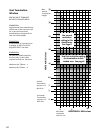
Figure 20. Blower attachment points.
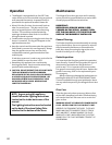
The blower will ONLY come on when the switch is in
the Hi or Low position and ONLY when the snapstat
(thermodisc) is heated by the operation of the stove.
(Approximately 10- 20 minutes after the stove has
been running).
IMPORTANT: IF THE OPTIONAL FORCED
BLOWER KIT(PART # 129161) IS TO BE
INSTALLED ON THE STOVE AT THE TIME
OF THE INSTALLATION OR IN THE
FUTURE, THE GAS SUPPLY LINE
SHOULD BE INSTALLED AS CLOSE TO
THE FLOOR AS POSSIBLE. USE OF A 90°
DIRECTLY OFF THE VALVE WILL ALLOW
FOR PROPER CLEARANCE FOR THE
BLOWER. SEE FIG. 18.
Optional Blower Installation
Figure 21. Blower position installed.
17