


20
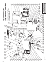
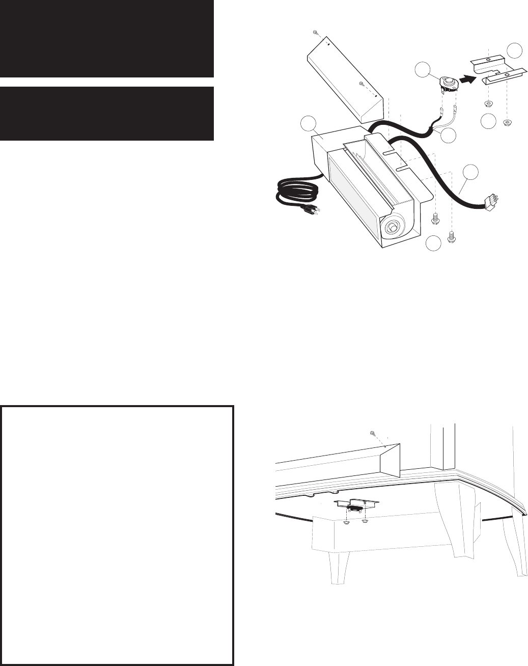
Optional Blower # 155620
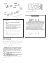
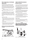
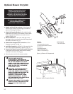
Figure 33. Blower Kit Components
THIS BLOWER MUST BE
ELECTRICALLY GROUNDED IN
ACCORDANCE WITH LOCAL CODES
OR, IN THE ABSENCE OF LOCAL
CODES, WITH THE CURRENT ANSI/
NFPA 70, NATIONAL ELECTRICAL
CODE OR CSA C22.1-CANADIAN
ELECTRICAL CODE.
THIS UNIT IS SUPPLIED WITH A
THREE-PRONG (GROUNDING)
PLUG FOR PROTECTION AGAINST
SHOCK HAZARD AND SHOULD BE
PLUGGED DIRECTLY INTO A
PROPERLY GROUNDED THREE-
PRONG RECEPTACLE. DO NOT
CUT OR REMOVE THE GROUNDING
PRONG FROM THE PLUG.
ALWAYS DISCONECT THE POWER
SUPPLY WHEN PERFORMING ANY
SERVICE ON THE FIREPLACE
INSERT.
1. Unpack and check the contents of the blower kit.
Contact your dealer if any damage is evident or
parts are missing. See fig. 33.
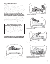
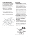
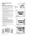
2. Attach the Snapstat Bracket to the studs located
underneath the stove in the middle of the firebox
floor using the two M6 hex nuts and a 10 mm
wrench. See fig. 34.
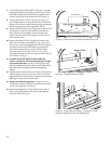
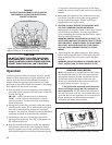
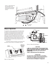
3. Attach the Blower to the stove with the screen
opening to the rear using the two M6 flange head
hex bolts as shown in fig. 35.
4. Attach either Snapstat wire connector to either
Snapstat terminal. See fig. 35.
5. Install the Snapstat by sliding it all the way into the
slot in the Snapstat Bracket as shown in fig. 34.
6. Connect the female Control Switch quick-connector
to the male control switch wire harness already
installed in the stove. See fig. 35.
7. Connect power cord to the nearest outlet.
Contents
1. Blower
2. Snapstat Wire Harness
3. Control Switch Wire Harness
4. Snapstat
5. Snapstat Bracket
6. M6 Flange Nuts, (2)
7. M6 x 12 Hex Bolts, (2)
Tools Required
• 10 mm wrench
Figure 34. Attach Snapstat Bracket.
Snapstat
Bracket
Hex Head
Flange Nuts
2
3
6
5
4
1
7
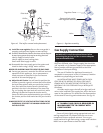
CONNECT THE GAS SUPPLY TO THE
STOVE BEFORE INSTALLING THIS
BLOWER. IF NECESSARY, USE A 90°
ELBOW OFF THE GAS VALVE TO CREATE
ADEQUATE GAS LINE CLEARANCE.
BE SURE ALL WIRE CONNECTIONS
HAVE BEEN MADE BEFORE
CONNECTING TO POWER SUPPLY.