


17
System Check
1. PURGING THE GAS LINE: When lighting the appli-
ance for the first time, it will take a few moments to
clear the gas line of air. Once this purge is complete,
the appliance will operate as described in the
lighting instructions. See the inside back cover of
this manual or the stove Rating Plate attached the
bottom of the stove. Subsequent burner starts will
not require purging the gas line unless the supply
line is shut off.
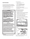
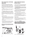
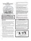
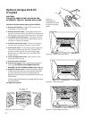
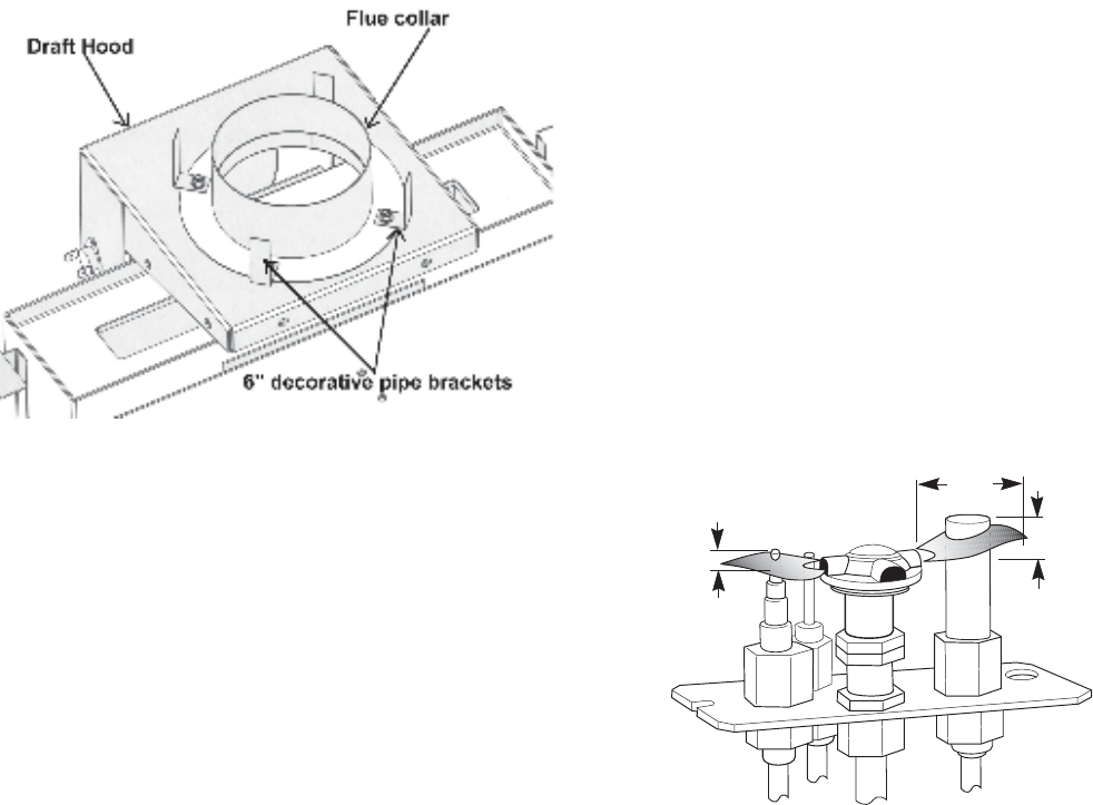
2. PILOT FLAME: You can monitor the pilot flame
through the view port located at the rear of the
Right Log. See fig. 28. The pilot flame should be
steady - not lifting or floating. The flame should be
blue in color around the pilot hood, with traces of
yellow toward the outer edges.
The pilot flame should engulf the top 3/8” of the
thermopile (to generate millivolt current) and the
top 1/8” of the thermocouple. The pilot flame
should project out of the pilot hood 1” at all three
ports. See fig. 28.
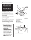
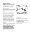
3. BURNER ADJUSTMENT: This stove is equipped with a
variable gas control valve that allows easy adjust-
ment of the flame height appearance and heat
output. To adjust the flame between the HI and
LOW setting, rotate the HI/LOW knob, located in the
center of the valve face. Fire intensity can be
adjusted up to 50% between the LOW and HIGH
settings. See fig. 29.
NO SMOKE OR SOOT SHOULD BE PRESENT. CHECK
LOG PLACEMENT IF ANY SOOT OR SMOKE IS
PRESENT. IF SOOT OR SMOKE PERSISTS, THE AIR
SHUTTER MAY NEED TO BE ADJUSTED.
See Air Shutter/Flame Appearance section of this
manual for proper air shutter settings and adjust-
ments. Note: the more offsets there are in the vent
system, the greater the need for an air shutter
adjustment. See page 16.
1
(25mm)
3/8
(8mm)
Min.
1/8
(3mm)
Min.
Figure 28. Proper pilot flame appearance.
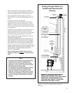
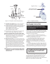
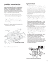
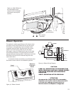
Installing Decorative Pipe
The use of decorative pipe is optional. No decorative
pipe is included with the Jøtul GF 300 BV Allagash,
however, four locator brackets are included with
the stove in the hardware bag. The brackets are
used to center the decorative pipe over the draft
hood on which the pipe rests. Follow the procedure
below to attach the brackets to the stove.
1. Remove the four 1/4” hex head screws that
attach the 4” Flue Collar to the draft hood, but
do not remove the Flue Collar. See Figure 27.
2. Align the “L”- shaped pipe brackets with the
holes on the Flue Collar and attach using the
four 1/4” hex head screws, located in the Misc.
Hardware Bag.
Reminder: Do not use single wall stove pipe as the
vent pipe on this appliance.
Figure 27. Decorative pipe attachment.
Spill
Switch