


16
Close
Open
Optional Wall Thermostat or
Remote Control
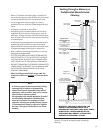
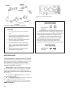
Use only a 750 millivolt DC two-wire circuit thermostat
with this appliance. The thermostat should be placed in
the same room as the heater, typically 5 feet off the
floor. Avoid drafty areas or any area that may affect the
accuracy of the thermostat.
The thermostat should be connected to the GF 300
BV using a minimum of 16 gauge wire with a maximum
length of 25 feet of wire.
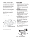
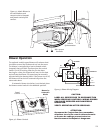
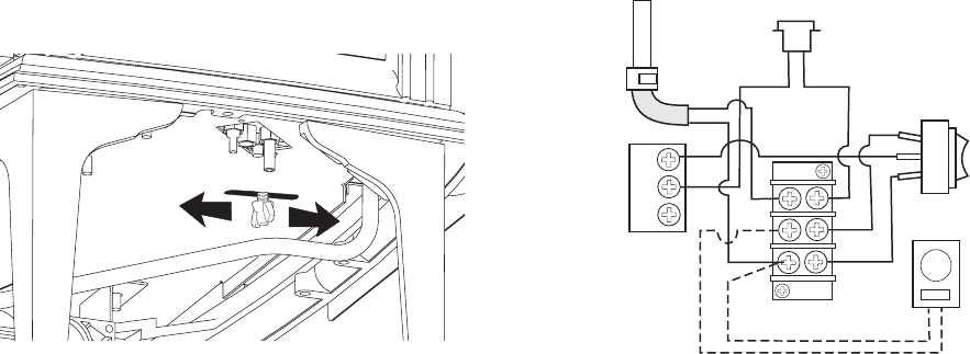
Connect the two thermostat wire leads to the two
lower terminals on the terminal block located directly
above the ignitor button. Do not overtighten the
connections. IT IS NOT NECESSARY TO DISCONNECT
ANY OTHER WIRES. See Fig. 26.
For thermostatic operation, the On/Off/T-Stat
switch on the back of the stove must be in the T-stat
position, and the pilot light must be running, as it is the
power source for the thermostat.
At the thermostat, the two wires should be con-
nected to the two connection screws on the thermostat
base plate per the manufacturer’s instructions.
Remote Control
When using a remote, the remote receiver should be
wired to the terminal block the same way the thermo-
stat would be. See the instructions above.
Follow the operating instructions included with the
Remote Control unit.
CAUTION:
LABEL ALL WIRES PRIOR TO DISCONNECTION
WHEN SERVICING THE CONTROLS. WIRING
ERRORS CAN CAUSE IMPROPER OR DANGEROUS
OPERATION. ALWAYS VERIFY PROPER OPERA-
TION AFTER SERVICING THE APPLIANCE.
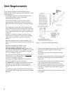
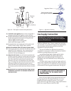
Figure 26. Valve and Accessory wiring diagram.
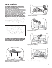
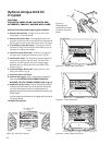
Flame Appearance / Air Shutter
Adjustment
The GF 300 BV gas stove is shipped from the factory
equipped to burn Natural gas. If the stove has been
converted for use with propane, the Air Shutter may
require adjustment to achieve the desired flame appear-
ance. Other installation related variables can also affect
the flame picture. The Air Shutter may be opened or
closed to provide the best flame picture for your specific
installation.
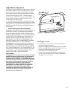
Too large an air opening - the appliance will generate
a flame that is blue and transparent, or an “anemic”
flame.
Too small an air setting - the appliance will generate
very long yellow flames resulting in soot. Sooting pro-
duces black deposits on the logs, on the inside walls of
the appliance, and potentially on the exterior termination
cap. Sooting is caused by incomplete combustion in the
flames and lack of combustion air entering the air shutter
opening.
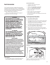
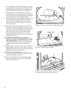
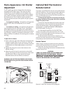
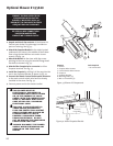
To adjust the air shutter:
1. Reach under the right side of the stove and loosen the
wingnut located closest to you. See fig. 25. Slide the
wingnut stud forward to open the air shutter and back
to provide less air. Make adjustments in small incre-
ments.
2. Tighten the wingnut to secure the shutter at the
desired setting.
3. Allow the stove to burn for 30 minutes on the HIGH
setting, observing the flame continuously. If the flame
appears weak, slow, or sooty, repeat the process
described above until the flame is as desired.
WARNING: AIR SHUTTER ADJUSTMENTS SHOULD ONLY
BE PERFORMED BY A QUALIFIED PROFESSIONAL SERVICE
TECHNICIAN.
Figure 25. Loosen the wingnut to adjust the air shutter.
VALVE
TH
TP
TH
TP
TERMINAL
BLOCK
THERMOPILE
ROCKER
SWITCH
ON
OFF
TSTAT
Yellow
Purple
SPILL SWITCH
White
Orange
Red
Black
White
Black
OPTIONAL
THERMOSTAT
or
REMOTE
CONTROL