


13
Gas Supply Connection
The gas supply line connection is made to the left side of
the front-mounted valve. The gas supply line should be
3/8" npt with a 1/2" diameter supply, or the appropriate
size to provide sufficient gas pressure to the valve
regardless of the input setting.
The use of Flexible Gas Appliance Connectors is
acceptable in many areas in the U.S. However, Canadian
methods vary depending on local code.
ALL INSTALLATIONS MUST COMPLY WITH LOCAL
CODE OR IN THE ABSENCE OF LOCAL CODE, MUST
COMPLY WITH THE MOST RECENT EDITION OF THE
NATIONAL FUEL GAS CODE ANSI Z223.1/NFPA 54 OR
CAN-B149.
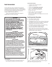
All codes require a gas shut-off valve (gas cock) and
union, to be installed in the supply line, and in the same
room as the appliance. This allows for the disconnection
of the stove for servicing and maintenance. See fig. 18.
A T-HANDLE GAS COCK IS REQUIRED IN
MASSACHUSETTS TO COMPLY WITH
CODE 248CMR.
Secure all joints tightly using appropriate tools and
sealing compounds. For propane units be sure to use
compounds that are propane resistant. Turn on gas
supply and test for gas leaks using a soapy water solution.
Never use an open flame to check for leaks.
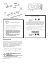
15. Install the new regulator: Be sure the new gasket is
properly positioned and tighten screws securely.
16. Install the identification labels to the stove so that they can
be seen by any person that may be servicing the stove.
Label A: apply to back of stove.
Label B: apply to stove’s rating plate.
Small valve Label: apply to valve.
17. Reassemble the stove, apply gas to the system and
check for leaks using a soapy water solution.
NEVER USE AN OPEN FLAME TO CHECK FOR GAS LEAKS.
18. Correct gas pressure is essential for efficient and safe
operation of this appliance. Use a manometer to
check pressures as specified in the Gas Pressure
section of this manual (page 15).
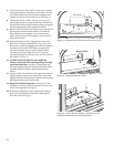
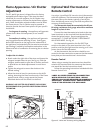
19. Adjust the Air Shutter. You will need to position the
shutter to provide a gas/air mixture that will achieve
the best flame picture with your particular installa-
tion. Start with the shutter stem at the half-way
position in the slot in the bottom of the stove. See
fig. 12. Pushing the stem back will restrict air, while
pushing it forward will open the shutter and in-
crease air. With some experimentation, you will find
the shutter position that works best for your installa-
tion.
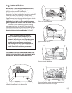
ALWAYS REFER TO THE LIGHTING INSTRUCTIONS ON THE
INSIDE BACK COVER OF THIS MANUAL WHEN LIGHT-
ING YOUR STOVE.
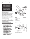
BLOWER NOTE: Install the optional blower before
connecting the gas line in order to ensure adequate
clearance between both.
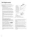
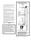
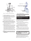
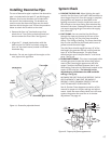
Valve
Figure 17 Regulator assembly.
Remove black gasket
from regulator assembly
Regulator Tower
Pilot Head
Orifice
Pilot Base
Figure 16. Pilot orifice removal and replacement.
Retainer
Clip