


26 © 2001 Directed Electronics, Inc. Vista, CA
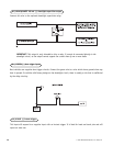
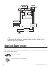
table of zones
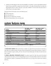
When using the diagnostic functions, use the Table of Zones to determine which input has triggered the system.
It is also helpful in deciding which input to use when connecting optional sensors and switches.
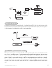
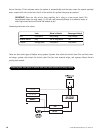
rapid resume logic
This DEI system will store its current state to non-volatile memory. If power is lost and then reconnected the
system will recall the stored state from memory. This means if the unit is in Valet mode and the battery is dis-
connected for any reason, such as servicing the car, when the battery is reconnected the unit will still be in Valet
mode. This applies to all states of the system including arm, disarm, and Valet mode.
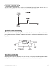
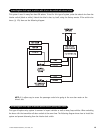
troubleshooting
■ Shock sensor does not trigger the alarm.
Has Nuisance Prevention Circuitry (NPC) been triggered? If so, you will hear five chirps when disarming. To check
this, turn the ignition key on and off to clear NPC memory, and then retest the shock sensor. For a detailed
description of NPC, refer to the owner’s guide.
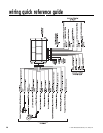
ZONE NO. TRIGGER TYPE INPUT DESCRIPTION
1 Instant H1/6 BLUE wire. Connect to optional hood/trunk pins.
2 Multiplexed Heavy impact detected by the on-board shock sensor.
3 Two-stage, progresses from Door switch circuit. H1/5 GREEN or H1/7 VIOLET.
warning to full alarm
4 Multiplexed Optional sensor. BLUE and GREEN wire on the 4-pin sensor
plug.
5 Two-stage (similar to doors) Ignition input. H1/9 YELLOW.
NOTE: The Warn Away response does not report on the LED.