


© 2001 Directed Electronics, Inc. Vista, CA 21
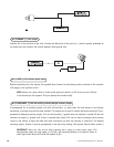
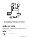
3. Press and HOLD the Valet/program for three seconds.
4. The LED will flash once to confirm the lock polarity was learned.
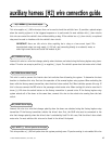
plug-in harnesses
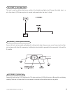
The super-bright LED operates at 2VDC. Make sure the LED wires are not shorted to ground as the LED will be
damaged. The LED fits into a
9
/32-inch mounting hole. Be sure to check for clearance prior to drilling the mount-
ing hole.
The Valet/program switch should be accessible from the driver’s seat. It plugs into the blue port on the side of
the control module. Since the system features Valet by remote, the switch can be well hidden. Consider how the
switch will be used before choosing a mounting location. Check for rear clearance before drilling a
9
/32-inch hole
and mounting the switch. The GRAY wire in the two-pin plug may also be used as a (+) ghost switch input and
can be connected to any (+) switch in the vehicle. (See the Feature Menu section of this guide.)
NOTE: Please note for the customer the location of the Valet/program switch in the space provided
in the Owner’s Guide.
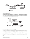
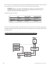
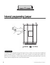
on-board stinger doubleguard shock sensor
There is a dual-stage shock sensor inside the control unit. Adjustments are made via the rotary control as indi-
cated in the following diagram. Since the shock sensor does not work well when mounted firmly to metal, we
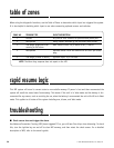
recommend against screwing down the control module. The full trigger of the on-board shock sensor reports zone 2.
See the Table of Zones section of this guide.
NOTE: When adjusting the sensor, it must be in the same mounting location that it will be after
the installation is completed. Adjusting the sensor and then relocating the module requires
readjustment.
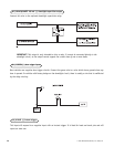
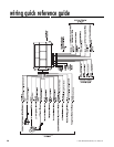
valet/program switch, 2-pin blue plug
super-bright LED, 2-pin white plug