


12 © 2001 Directed Electronics, Inc. Vista, CA
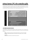
primary harness (H1) wire connection guide
This guide describes in detail the connection of each wire. Also included are possible applications of each wire.
This system was designed with the ultimate in flexibility and security in mind. Many of the wires have more than
one possible function. Please read carefully to ensure a thorough understanding of this unit.
______
______
______
______
______
______
______
______
______
______
______
______
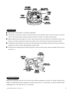
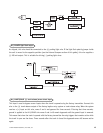
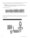
This wire supplies a (-) ground as long as the system is armed. This output ceases as soon as the system is dis-
armed. This wire controls operation of the optional starter kill relay and can be used to control other optional
accessories.
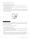
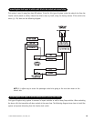
NOTE: If connecting the orange wire to control another module, such as a 529T or 530T window
controller, a 1 amp diode (type 1N4004) will be required. Insert the diode as shown in the follow-
ing diagram.
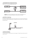
IMPORTANT! Never interrupt any wire other than the starter wire.
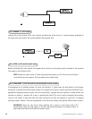
H1/1 ORANGE (-) ground-when-armed output
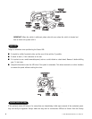
RED/WHITE (-) 200 mA CHANNEL 2 OR DELAYED ACCESSORY OUTPUT
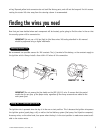
RED (+) CONSTANT POWER INPUT
BROWN (+) SIREN OUTPUT
YELLOW (+) SWITCHED IGNITION INPUT, ZONE 5
BLACK (-) CHASSIS GROUND INPUT
VIOLET (+) DOOR TRIGGER INPUT, ZONE 3
BLUE (-) INSTANT TRIGGER INPUT, ZONE 1
GREEN (-) DOOR TRIGGER INPUT, ZONE 3
BLACK/WHITE (-) 200 mA DOMELIGHT SUPERVISION OUTPUT
WHITE/BLUE (+) TRUNK RELEASE INPUT, SENSOR BYPASS
WHITE (+)/(-) SELECTABLE LIGHT FLASH OUTPUT
ORANGE (-) 500 mA ARMED OUTPUT
H1/1
H1/2
H1/3
H1/4
H1/5
H1/6
H1/7
H1/8
H1/9
H1/10
H1/11
H1/12