


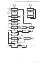
S9360A, S9361A, S9370A, S9371A INTEGRATED BOILER CONTROLLERS
9 69-2076—01
a
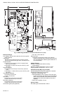
Indicates optional connection based on configuration.
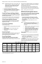
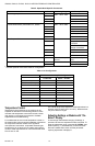
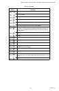
HSI Model Specific Connectors
In addition to the common connectors listed above, Table 4 identifies connectors available on the HSI model board
assemblies.
a
Indicates optional connection based on configuration.
EnviraCOM/Black 1 of 3 Stripped Bare Wire ECOM Data “1”
2 of 3 ECOM R “2”
3 of 3 ECOM C “3”
EnviraCOM Diag/
White
1 of 3 “Pen” Diagnostic Tool
with 0.1 in. spacing
ECOM Data “1”
2 of 3 ECOM R “2”
3 of 3 ECOM C “3”
Transformer Primary/
White
1 of 3
Molex
®
50-81-1030
L1
2 of 3 Earth Ground
3 of 3 Neutral
Transformer
Secondary/White
1 of 2
Molex
®
50-81-1020
24 Vac Input
2 of 2 Earth Ground
“Control”/White 1 of 9
Molex
®
50-81-1090 Pressure Switch
a
2 of 9
Pilot Valve
a
3 of 9
Pressure Switch
a
4 of 9 AC N.C. Switch
5 of 9 Main Valve
6 of 9 AC N.C. Switch
7 of 9 N.C.
8 of 9 MV/PV (Valve
Common)
9 of 9 N.C.
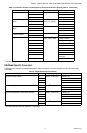
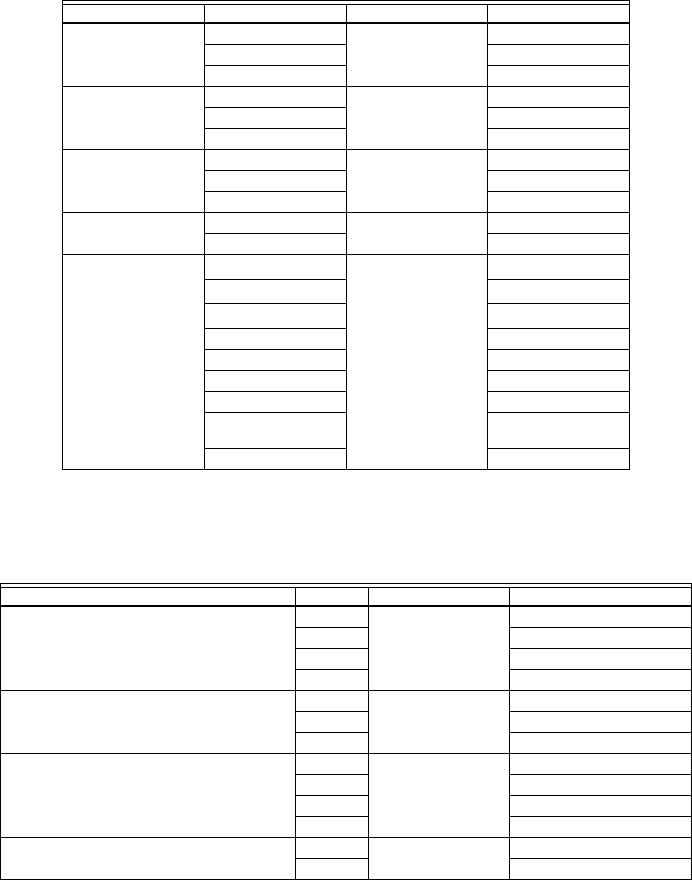
Table 3. Connectors Common to Both Spark-to-Pilot and Hot Surface Ignition Options. (Continued)
Connection/Color Pin Mating Plug Description
Table 4. HSI Model Specific Connectors.
Connection Pin Mating Plug Description
On/Off Circulator
a
/White
1 of 4
Molex
®
50-84-1061
L1 Relay Out
2 of 4 Earth Ground
3 of 4 Neutral
4 of 4 Neutral
Line Voltage Input/Red 1 of 3
Molex
®
50-84-1031
L1
2 of 3 Earth Ground
3 of 3 Neutral
Induced Draft Blower (Combustion Air)/Red 1 of 4
Molex
®
50-84-1041
L1 Relay Out
2 of 4 Earth Ground
3 of 4 Neutral
4 of 4 Neutral
HSI/Red 1 of 2
Molex
®
50-84-1021
L1 Relay Out
2 of 2 Flame Sense/(N) Relay Out