


S9360A, S9361A, S9370A, S9371A INTEGRATED BOILER CONTROLLERS
11 69-2076—01
“SP_” Setpoint.
“Df_” Setpoint Differential (select models).
“°F_” Degrees Fahrenheit
Then press the UP or DOWN button until the parameter
has reached the desired value. After 60 seconds without
any button inputs, the control will automatically return to
the READ mode.
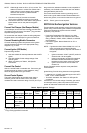
Display
In the RUN mode, status items and parameters are
viewable. For example, to display setpoint, the control will
flash “sp” (setpoint) followed by the temperature (i.e.,
135), followed by °F or °C.
To read settings, press and release the I key to find the
parameter of interest. For example, press and release I
until setpoint (sp) is displayed, followed by a three-digit
number, i.e., 220, followed by °F or °C. Pressing the I
button again will display the (S1T) Sensor 1 Temperature
followed by a three-digit number and the corresponding
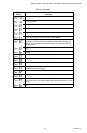
degree designator. See Display Readout, Fig. 6.
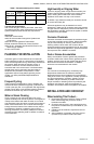
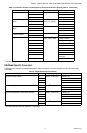
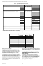
Fig. 6. Display readout definitions.
Boiler Temperature Controller
When the water temperature reaches setpoint, the
controller ends the heating cycle. When the water
temperature drops below the setpoint minus the
differential, the control restarts a heat cycle to re-heat the
tank of water.
If the water temperature exceeds the max allowed
temperature, the control enters a manual reset lockout
state. For models that have reset capability, press any on-
board button (when present), cycle power, or use the
remote display to reset.
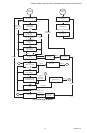
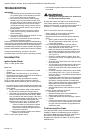
CHECKOUT
Put the system into operation and observe operation
through at least one complete cycle to make sure that the
controller operates properly. See Troubleshooting section
to assist in determining system operation.
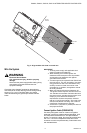
LOCATION AND MOUNTING
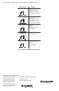
Sensing Bulb(s)
The water heater manufacturer usually provides a tapping
for the sensing bulb at a point where average water
temperature can be measured. Some water heaters use
two (2) sensors, one limit rated near the center or bottom
of the tank, the other non-limit rated near the top. See Fig.
7. Follow the heater manufacturer instructions.
The sensing bulb can be installed in an immersion well.
Wells and fittings must be ordered separately. See 68-
0040.
When an immersion well is used, the sensor should fit
snugly and should touch the bottom of the well for best
temperature response. Use heat-conductive compound
(Honeywell part no. 107408) to fill the space between the
bulb and the well to improve heat transfer characteristics
(optional). Make sure the sensor is held firmly in the well.
Remote Display
For units that use a remote display, refer to I&I sheet for
SD7000A.
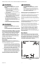
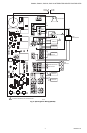
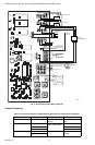
WIRING
IMPORTANT:
For maximum trouble free operation, run the
sensor leadwires separately from any other cur-
rent-carrying wires.
All wiring must comply with local codes and ordinances.
Disconnect power supply before beginning wiring.
Connect according to water heater manufacturer
instructions.
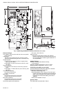
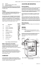
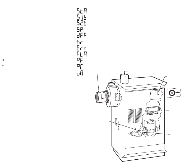
Fig. 7. Typical location of limit function sensor and
control module.
Setpoint
Text Description
Di
sp
l
ay
Shows
sp
Current State
Sensor 1 Temperature
Sensor 2 Temperature*
sta
s1t
s2t
Setpoint Differentialdff
Heat Request Statushr
Flame Currentfla
Degrees Fahrenheit F
Error Codeerr
Micro Amps
uA
M24052
Degrees Celsius C
M27076
PILOT
MAIN
BURNER
INLET
INTEGRATED
BOILER
CONTROL
INDUCER
MOTOR
(OPTIONAL)
SUPPLY
PUMP
LIMIT
SENSOR