


S9360A, S9361A, S9370A, S9371A INTEGRATED BOILER CONTROLLERS
69-2076—01 6
NOTE: Cable length must be 36 in. (0.9 m) or less. The
cable must not be in continuous contact with a
metal surface or spark voltage will be greatly
reduced. Use ceramic or plastic standoff
insulators as required.
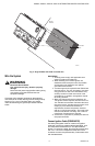
1. Connect one end of the cable to the male
quick-connect SPARK terminal on the module.
2. Connect the other end of the cable to the igniter or
igniter-sensor stud on the pilot burner/igniter-
sensor.
Connect Vent Damper (Vent Damper Models)
A vent damper can be used with modules provided with a
vent damper plug connector. The Molex
®
plug provided
simplifies wiring connections.
To connect the vent damper, follow the wiring diagrams
supplied with the vent damper for typical connections.
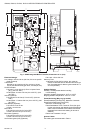
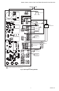
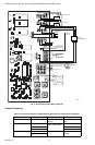
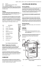
Connect Remaining Module Connectors
Connect remaining system components to the ignition
module terminals as shown in the appropriate wiring
diagrams, Fig. 4 and 5.
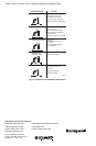
Connect Igniter (HSI Models)
Prepare wiring harness:
1. Use wire suitable for the temperatures near the HSI
igniter.
2. Use wire suitable for the voltage ratings of the
specific igniter.
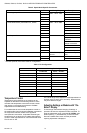
3. Attach connector per Table 4, HSI Specific
Connectors.
Connect Gas Control
Use No. 18 AWG solid or stranded wire. Connect to gas
control terminals as shown in wiring diagrams, using
terminals appropriate to the gas control.
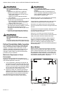
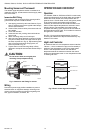
Ground Control System
The igniter, flame sensor and module must share a
common ground with the main burner. Use AWM
insulated wire with a minimum rating of 105°C (221°F) for
the ground wire; asbestos insulation is not acceptable. If
necessary, use a shield to protect the wire from radiant
heat generated by the burner.
The burner serves as the common grounding area. If
there is not a good metal-to-metal contact between the
burner and ground, run a lead from the burner to ground.
NOTE: “Earth” ground is not required.
S937XA Hot Surface Ignition Versions
These models provide operating control of a direct ignition
system using a hot surface igniter. Additional components
required to complete the system must be ordered
separately. They include:
• Dual Valve Combination Gas Control: Any direct
ignition gas control with 2.0A maximum main valve
rating. VR8205, VR845, VR854, VR8450, or VR8540
recommended.
• Hot Surface Igniter: Norton Model 201 or 271 or
equivalent.
NOTE: If igniter other than Norton Model 201 or 271 is
used, the igniter must meet the following
minimum specifications, required over the life of
the igniter:
1. Igniter must reach 1000°C (1832°F) within 34
seconds with 102 Vac applied.
2. Igniter must maintain at least 500 megohms
insulation resistance between the igniter
leadwires and the igniter mounting bracket.
3. Igniter current draw at 132 Vac must not
exceed 5 A.
Sensor: Separate sensor required. Honeywell Q354
recommended.
Igniter Wiring: Provide wiring harness to suit application.
• Leadwires: No. 18 AWG, stranded copper with 105°C
rated, 1/16 in. AWM insulation.
• Terminals: Insulated. See Table 4 for HSI specific
connectors.
Transformer: Add current ratings of module, gas control,
vent damper and any other components of the control
system to determine transformer size requirements.
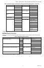
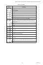
Table 2. Specific Ignition Timings.
a
Ignition Activation Period is the time that the hot surface igniter remains powered after the gas valve opens.
b
Purge Timing specified in seconds.
Model Ignition Type Draft Type
No. of
Ignition
Trials
Igniter/
Sensor
Type
Automatic
Restart
Time
Ignition
Activation
Period
a
Prepurge
Timing
b
Postpurge
Timing
b
S9360A Intermittent
Pilot - Spark
Induced 3 Separate 1 hour N/A 15 5
S9360A Intermittent
Pilot - Spark
Atmospheric 3 Separate 1 hour N/A 1 5
S9370A Direct Hot
Surface
Induced 3 Separate 1 hour 2.5 5 15