


S9360A, S9361A, S9370A, S9371A INTEGRATED BOILER CONTROLLERS
69-2076—01 10
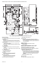
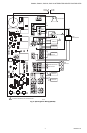
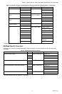
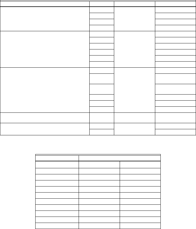
Table 5. Spark Model Specific Connectors.
a
Indicates optional connections based on configuration.
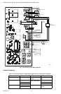
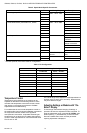
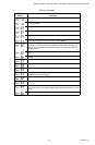
Table 6. Pin Configuration.
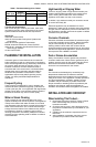
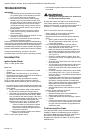
Temperature Control
Temperature control setpoint on the module can be
adjusted as described in the following sections. Some
modules with temperature control also include a three-
digit display on the printed circuit board to facilitate
adjustments and troubleshooting.
For modules that do not include temperature control on
the module refer to the Honeywell Installation Instructions
for the specific interface module or the appliance
manufacturer’s instructions. A separate automatic gas
shutoff device is not required in a system that uses this
control to meet requirements for CSA International ANSI
Z21.87 and UL 353.
The overall range of the setpoint is model-dependent but
is within 130°F to 240°F (54°C to 116°C). Select devices
may have different ranges.
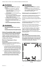
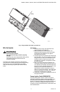
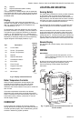
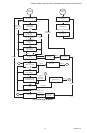
Adjusting Settings or Models with “On-
Board” Display
To discourage unauthorized changing of settings, a
procedure to enter the adjustment mode is required. To
enter the adjustment mode, press the UP, DOWN, and I
buttons (see Fig. 1) simultaneously for three seconds.
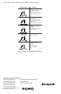
Press and release the I button until the parameter
requiring adjustment is displayed:
Connection Pin Mating Plug Description
Line Voltage Input/White 1 of 4
Molex
®
50-81-1040
L1
2 of 4 Earth Ground
3 of 4 Earth Ground
4 of 4 Neutral
Induced Draft Blower (Combustion Air
a
)/White
1 of 6
Molex
®
39-01-2060
Earth Ground
2 of 6 N/C
3 of 6 Neutral
4 of 6 N/C
5 of 6 L1 Relay Out
6 of 6 N/C
Vent Damper
a
/White
1 of 6 24 Vac
2 of 6 Damper E.S.
Feedback
3 of 6 24V Common if
damper connected
4 of 6 24V Common
5 of 6 Damper Activation
6 of 6 N/C
Spark Rod 1 of 1 1/4 in. female quick-
connect
Connection to Spark
Rod
On/Off Circulator
a
/Red
1 of 2
Molex
®
50-84-1021
L1 Relay Out
2 of 2 Neutral
Wire Harness Housing Pin Configuration
Pin/Socket Molex
®
Number
Line In pin 02-08-2004
Transformer Primary socket 02-08-1002
Transformer Secondary socket 02-08-1002
Circulator pin 02-08-2004
Damper pin 03-06-2103
Inducer socket 39-00-0039
Control socket 02-08-1002
Sensor 1 socket 08-50-0106
Sensor 2 socket 08-50-0106
E-COM Diagnostic socket 08-50-0114