


S9360A, S9361A, S9370A, S9371A INTEGRATED BOILER CONTROLLERS
5 69-2076—01
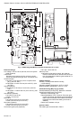
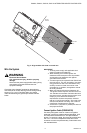
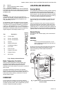
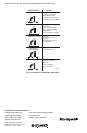
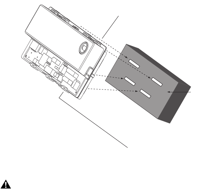
Fig. 3. Align module with slots in control box.
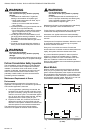
Wire the System
WARNING
Electrical Shock Hazard.
Can cause severe injury, death or property
damage.
Disconnect the power supply before making wiring
connections to prevent electrical shock or
equipment damage.
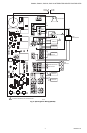
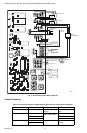
Check the wiring diagram furnished by the appliance
manufacturer for circuits differing from the wiring hookup
shown in Fig. 4 and 5. Carefully follow any special
instructions affecting the general procedures outlined
below.
IMPORTANT
1. All wiring must comply with applicable local
electrical codes and ordinances.
2. When installing a hot surface igniter, the
leadwires should be kept as short as possible
and should not be allowed to rest against
grounded metal surfaces.
3. A common ground is required for the S93XX and
the main burner. The 24V “secondary” plug inter-
nally grounds one side of the transformer. Any
auxiliary controls or limits must not be in the
grounded leg. In addition, the appliance should
be earth-grounded.
4. Make sure the transformer has adequate VA.
The ignition module requires at least 0.2A at 24
Vac. Add the current draws of all other devices in
the control circuit, including the gas control, and
multiply by 24 to determine the total VA
requirements of these components. Add this
total to 5.0 VA (for the module). The result is the
minimum transformer VA rating. Use a Class II
transformer if replacement is required.
5. Check that L1 (hot) and L2 (neutral) are wired to
the proper terminals.
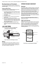
Connect Ignition Cable (S936XAXXXX)
Use Honeywell ignition cable or construct an ignition
cable that conforms to suitable national standards, such
as Underwriters Laboratories Inc. See Specifications
section. To construct a cable, fit one end (the module end)
with 1/4 in. connector receptacle and the other with a
connector to match the pilot assembly. Protect both ends
with insulated boots.
WATER
HEATER
CONTROL
BOX
M24229